
Page 476 - Automotive Engineering Powertrain Chassis System and Vehicle Body
P. 476
CHAP TER 1 5. 1 Modelling and assembly of the full vehicle
Δv
Z
Δγ
X
Y
Δz
Δx Δδ
Fxt
Fxb
Fy
Mz
Wheel
trajectory
Δy
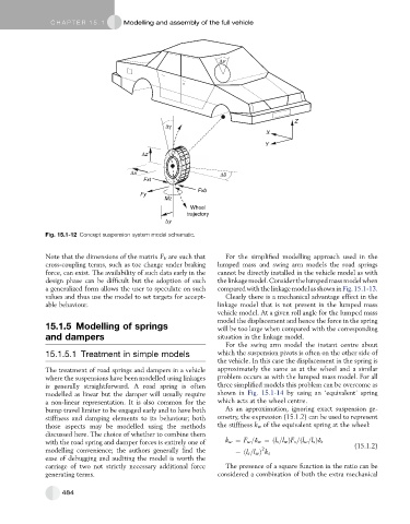
Fig. 15.1-12 Concept suspension system model schematic.
Note that the dimensions of the matrix F E are such that For the simplified modelling approach used in the
cross-coupling terms, such as toe change under braking lumped mass and swing arm models the road springs
force, can exist. The availability of such data early in the cannot be directly installed in the vehicle model as with
design phase can be difficult but the adoption of such thelinkagemodel.Considerthelumpedmassmodelwhen
a generalized form allows the user to speculate on such compared with thelinkage modelas shownin Fig. 15.1-13.
values and thus use the model to set targets for accept- Clearly there is a mechanical advantage effect in the
able behaviour. linkage model that is not present in the lumped mass
vehicle model. At a given roll angle for the lumped mass
model the displacement and hence the force in the spring
15.1.5 Modelling of springs will be too large when compared with the corresponding
and dampers situation in the linkage model.
For the swing arm model the instant centre about
15.1.5.1 Treatment in simple models which the suspension pivots is often on the other side of
the vehicle. In this case the displacement in the spring is
The treatment of road springs and dampers in a vehicle approximately the same as at the wheel and a similar
where the suspensions have been modelled using linkages problem occurs as with the lumped mass model. For all
is generally straightforward. A road spring is often three simplified models this problem can be overcome as
modelled as linear but the damper will usually require shown in Fig. 15.1-14 by using an ‘equivalent’ spring
a non-linear representation. It is also common for the which acts at the wheel centre.
bump travel limiter to be engaged early and to have both As an approximation, ignoring exact suspension ge-
stiffness and damping elements to its behaviour; both ometry, the expression (15.1.2) can be used to represent
those aspects may be modelled using the methods the stiffness k w of the equivalent spring at the wheel:
discussed here. The choice of whether to combine them
with the road spring and damper forces is entirely one of k w ¼ F w =d w ¼ðl s =l w ÞF s =ðl w =l s Þd s (15.1.2)
modelling convenience; the authors generally find the ¼ðl s =l w Þ k s
2
ease of debugging and auditing the model is worth the
carriage of two not strictly necessary additional force The presence of a square function in the ratio can be
generating terms. considered a combination of both the extra mechanical
484