
Page 471 - Automotive Engineering Powertrain Chassis System and Vehicle Body
P. 471
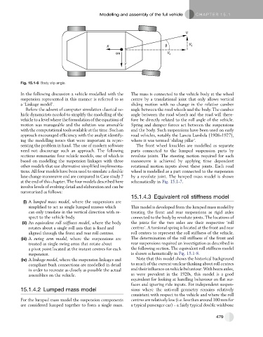
Modelling and assembly of the full vehicle   C HAPTER 15.1


                                                                                       V


                                                   X                          β          V y
                                                       cm                      V x

                                                           Y


           Fig. 15.1-6 Body slip angle.

           In the following discussion a vehicle modelled with the  The mass is connected to the vehicle body at the wheel
           suspension represented in this manner is referred to as  centre by a translational joint that only allows vertical
           a ‘Linkage model’.                                 sliding motion with no change in the relative camber
             Before the advent of computer simulation classical ve-  angle between the road wheels and the body. The camber
           hicle dynamicists needed to simplify the modelling of the  angle between the road wheels and the road will there-
           vehicle to a level where the formulation of the equations of  fore be directly related to the roll angle of the vehicle.
           motion was manageable and the solution was amenable  Spring and damper forces act between the suspensions
           with the computational tools available at the time. Such an  and the body. Such suspensions have been used on early
           approach encouraged efficiency with the analyst identify-  road vehicles, notably the Lancia Lambda (1908–1927),
           ing the modelling issues that were important in repre-  where it was termed ‘sliding pillar’.
           senting the problem in hand. The use of modern software  The front wheel knuckles are modelled as separate
           need not discourage such an approach. The following  parts connected to the lumped suspension parts by
           sections summarize four vehicle models, one of which is  revolute joints. The steering motion required for each
           based on modelling the suspension linkages with three  manoeuvre is achieved by applying time dependent
           other models that use alternative simplified implementa-  rotational motion inputs about these joints. Each road
           tions. All four models have been used to simulate a double  wheel is modelled as a part connected to the suspension
           lane change manoeuvre and are compared in Case study 7  by a revolute joint. The lumped mass model is shown
           at the end of this chapter. The four models described here  schematically in Fig. 15.1-7.
           involve levels of evolving detail and elaboration and can be
           summarized as follows:
                                                              15.1.4.3 Equivalent roll stiffness model
            (i) A lumped mass model, where the suspensions are
              simplified to act as single lumped masses which  This model is developed from the lumped mass model by
              can only translate in the vertical direction with re-  treating the front and rear suspensions as rigid axles
              spect to the vehicle body.                      connected to the body by revolute joints. The locations of
           (ii) An equivalent roll stiffness model, where the body  the joints for the two axles are their respective ‘roll
              rotates about a single roll axis that is fixed and  centres’. A torsional spring is located at the front and rear
              aligned through the front and rear roll centres.  roll centres to represent the roll stiffness of the vehicle.
           (iii) A swing arm model, where the suspensions are  The determination of the roll stiffness of the front and
              treated as single swing arms that rotate about  rear suspensions required an investigation as described in
              a pivot point located at the instant centres for each  the following section. The equivalent roll stiffness model
              suspension.                                     is shown schematically in Fig. 15.1-8.
           (iv) A linkage model, where the suspension linkages and  Note that this model shows the historical background
              compliant bush connections are modelled in detail  to much of the current unclear thinking about roll centres
              in order to recreate as closely as possible the actual  and their influence on vehicle behaviour. With beam axles,
              assemblies on the vehicle.                      as were prevalent in the 1920s, this model is a good
                                                              equivalent for looking at handling behaviour on flat sur-
                                                              faces and ignoring ride inputs. For independent suspen-
           15.1.4.2 Lumped mass model                         sions where the anti-roll geometry remains relatively
                                                              consistent with respect to the vehicle and where the roll
           For the lumped mass model the suspension components  centres are relatively low (i.e. less than around 100 mm for
           are considered lumped together to form a single mass.  a typical passenger car) – a fairly typical double wishbone


                                                                                                      479