
Page 470 - Automotive Engineering Powertrain Chassis System and Vehicle Body
P. 470
CHAP TER 1 5. 1 Modelling and assembly of the full vehicle
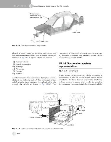
Anti-symmetry
constraints along
vehicle centre line
Force input
z
y
x Force input
Fig. 15.1-4 Finite element model of body-in-white.
plotted as time history graphs where the outputs are components of velocity of the vehicle mass centre V x and
computed in a reference frame fixed in the vehicle body as V y , measured in vehicle body reference frame, can be
indicated in Fig. 15.1-5. Typical outputs can include: used to readily determine this.
(i) Forward velocity
(ii) Lateral acceleration 15.1.4 Suspension system
(iii) Roll angle representation
(iv) Pitch angle
(v) Yaw rate 15.1.4.1 Overview
(vi) Roll rate
In this section the representation of the suspension as
Another measure often determined during test or sim- a component of the full vehicle system model will be
ulation is the body slip angle, b. This is the angle of the considered. As stated the use of powerful multibody
vehicle velocity vector measured from a longitudinal axis systems analysis programs often results in modelling
through the vehicle as shown in Fig. 15.1-6. The the suspension systems as installed on the actual vehicle.
Z
Yaw rate
PLANE Y-O
X
Roll angle
PLANE X-O
Y
Lateral acceleration
PLANE Z-O
Fig. 15.1-5 Typical lateral responses measured in vehicle co-ordinate frame.
478