
Page 474 - Automotive Engineering Powertrain Chassis System and Vehicle Body
P. 474
CHAP TER 1 5. 1 Modelling and assembly of the full vehicle
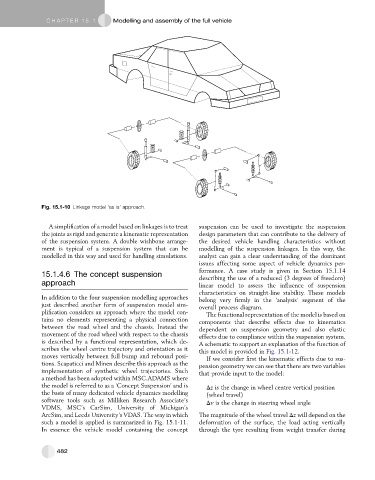
Fig. 15.1-10 Linkage model ‘as is’ approach.
A simplification of a model based on linkages is to treat suspension can be used to investigate the suspension
the joints as rigid and generate a kinematic representation design parameters that can contribute to the delivery of
of the suspension system. A double wishbone arrange- the desired vehicle handling characteristics without
ment is typical of a suspension system that can be modelling of the suspension linkages. In this way, the
modelled in this way and used for handling simulations. analyst can gain a clear understanding of the dominant
issues affecting some aspect of vehicle dynamics per-
formance. A case study is given in Section 15.1.14
15.1.4.6 The concept suspension describing the use of a reduced (3 degrees of freedom)
approach linear model to assess the influence of suspension
characteristics on straight-line stability. These models
In addition to the four suspension modelling approaches belong very firmly in the ‘analysis’ segment of the
just described another form of suspension model sim- overall process diagram.
plification considers an approach where the model con- The functional representation of the model is based on
tains no elements representing a physical connection components that describe effects due to kinematics
between the road wheel and the chassis. Instead the dependent on suspension geometry and also elastic
movement of the road wheel with respect to the chassis effects due to compliance within the suspension system.
is described by a functional representation, which de- A schematic to support an explanation of the function of
scribes the wheel centre trajectory and orientation as it this model is provided in Fig. 15.1-12.
moves vertically between full bump and rebound posi- If we consider first the kinematic effects due to sus-
tions. Scapaticci and Minen describe this approach as the pension geometry we can see that there are two variables
implementation of synthetic wheel trajectories. Such that provide input to the model:
a method has been adopted within MSC.ADAMS where
the model is referred to as a ‘Concept Suspension’ and is Dz is the change in wheel centre vertical position
the basis of many dedicated vehicle dynamics modelling (wheel travel)
software tools such as Milliken Research Associate’s Dv is the change in steering wheel angle
VDMS, MSC’s CarSim, University of Michigan’s
ArcSim, and Leeds University’s VDAS. The way in which The magnitude of the wheel travel Dz will depend on the
such a model is applied is summarized in Fig. 15.1-11. deformation of the surface, the load acting vertically
In essence the vehicle model containing the concept through the tyre resulting from weight transfer during
482