
Page 477 - Automotive Engineering Powertrain Chassis System and Vehicle Body
P. 477
Modelling and assembly of the full vehicle C HAPTER 15.1
LINKAGE MODEL LUMPED MASS MODEL
δ (I /I )δ w
s w
s
δ s
δ s
δ w l s δ w δ δ w
s
l w
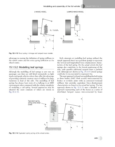
Fig. 15.1-13 Road spring in linkage and lumped mass models.
advantage in moving the definition of spring stiffness to Early attempts at modelling leaf springs utilized the
the wheel centre and the extra spring deflection at the simple approach based on equivalent springs to represent
wheel centre. the vertical and longitudinal force–displacement charac-
teristic of the leaf spring. On the actual vehicle the leaf
15.1.5.2 Modelling leaf springs springs also contribute to the lateral positioning of the
axle, with possible additional support from a panhard
Although the modelling of leaf springs is now rare on rod. Although not shown in Fig. 15.1-15 lateral springs
passenger cars they are still fitted extensively on light could also be incorporated to represent this.
trucks and goods vehicles where they offer the advantage The next approach is based on modelling the leaf spring
of providing relatively constant rates of stiffness for large as three bodies (SAE 3-link model) interconnected by
variations in load at the axle. The modelling of leaf bushes or revolute joints with an associated torsional
springs has always been more of a challenge in an MBS stiffness that provides equivalent force–displacement
environment when compared with the relative simplicity characteristics as found in the actual leaf spring. The last
of modelling a coil spring. Several approaches may be approach shown in Fig. 15.1-15 uses a detailed ‘as is’
adopted the most common of which are shown in approach representing each of the leaves as a series of
Fig. 15.1-15. distributed lumped masses interconnected by beam
l w
Equivalent spring
acting at the wheel
centre
k w
F s
k s
F w
δ s
δ w
l s
Fig. 15.1-14 Equivalent spring acting at the wheel centre.
485