
Page 484 - Automotive Engineering Powertrain Chassis System and Vehicle Body
P. 484
CHAP TER 1 5. 1 Modelling and assembly of the full vehicle
from the measured data and applied to the vehicle body. The gravitational constant is included in equation
A difficulty with such an approach is that the measured (15.1.12) to remind readers that this is a dynamic force.
results are for steady state in each condition and that If the model units are SI then GC is equal to 1. If as
transient effects are not included in the simulation. commonly used the model units for length are mm then
Consideration has been given to the use of a computa- GC is equal to 1000. When formulating the aerodynamic
tional fluid dynamics (CFD) program to calculate drag force it should be considered that the force acts at
aerodynamic forces and moments in parallel with (co- the CP and that this point generally moves as the vehicle
simulation) an MBS program solving the vehicle equations changes attitude. Similarly the drag coefficient C D and
of motion. The problem at the current time with this projected frontal area A also change as the body moves.
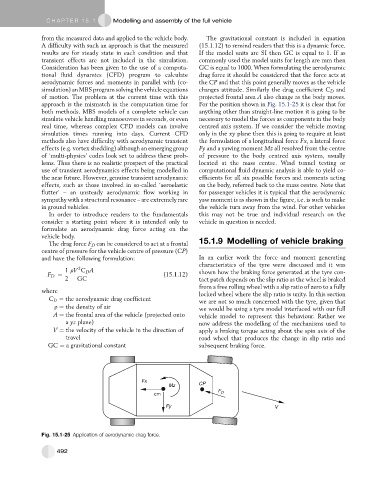
approach is the mismatch in the computation time for For the position shown in Fig. 15.1-25 it is clear that for
both methods. MBS models of a complete vehicle can anything other than straight-line motion it is going to be
simulate vehicle handling manoeuvres in seconds, or even necessary to model the forces as components in the body
real time, whereas complex CFD models can involve centred axis system. If we consider the vehicle moving
simulation times running into days. Current CFD only in the xy plane then this is going to require at least
methods also have difficulty with aerodynamic transient the formulation of a longitudinal force Fx, a lateral force
effects (e.g. vortex shedding) although an emerging group Fy and a yawing moment Mz all resolved from the centre
of ‘multi-physics’ codes look set to address these prob- of pressure to the body centred axis system, usually
lems. Thus there is no realistic prospect of the practical located at the mass centre. Wind tunnel testing or
use of transient aerodynamics effects being modelled in computational fluid dynamic analysis is able to yield co-
the near future. However, genuine transient aerodynamic efficients for all six possible forces and moments acting
effects, such as those involved in so-called ‘aeroelastic on the body, referred back to the mass centre. Note that
flutter’ – an unsteady aerodynamic flow working in for passenger vehicles it is typical that the aerodynamic
sympathy with a structural resonance – are extremely rare yaw moment is as shown in the figure, i.e. is such to make
in ground vehicles. the vehicle turn away from the wind. For other vehicles
In order to introduce readers to the fundamentals this may not be true and individual research on the
consider a starting point where it is intended only to vehicle in question is needed.
formulate an aerodynamic drag force acting on the
vehicle body.
The drag force F D can be considered to act at a frontal 15.1.9 Modelling of vehicle braking
centre of pressure for the vehicle centre of pressure (CP)
and have the following formulation: In an earlier work the force and moment generating
characteristics of the tyre were discussed and it was
2
1 rV C D A shown how the braking force generated at the tyre con-
F D ¼ (15.1.12)
2 GC tact patch depends on the slip ratio as the wheel is braked
from a free rolling wheel with a slip ratio of zero to a fully
where
locked wheel where the slip ratio is unity. In this section
C D ¼ the aerodynamic drag coefficient
we are not so much concerned with the tyre, given that
r ¼ the density of air we would be using a tyre model interfaced with our full
A ¼ the frontal area of the vehicle (projected onto vehicle model to represent this behaviour. Rather we
a yz plane) now address the modelling of the mechanisms used to
V ¼ the velocity of the vehicle in the direction of apply a braking torque acting about the spin axis of the
travel road wheel that produces the change in slip ratio and
GC ¼ a gravitational constant subsequent braking force.
Fx
Mz CP
cm F D
Fy V
Fig. 15.1-25 Application of aerodynamic drag force.
492