
Page 483 - Automotive Engineering Powertrain Chassis System and Vehicle Body
P. 483
Modelling and assembly of the full vehicle C HAPTER 15.1
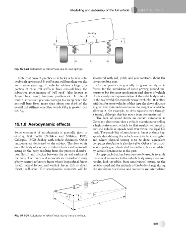
Fig. 15.1-23 Calculation of roll stiffness due to road springs.
Note that current practice in vehicles is to have rela- associated with roll, pitch and yaw rotations about the
tively soft springs and fit stiffer anti-roll bars than was the corresponding axes.
norm some years ago. If vehicles achieve a large pro- Current practice is generally to ignore aerodynamic
portion of their roll stiffness from anti-roll bars, the forces for the simulation of most proving ground ma-
subjective phenomenon of ‘roll rock’ (also known as noeuvres but for some applications and classes of vehicle
‘lateral head toss’) becomes problematic. A rule of this is clearly not representative of the vehicle dynamics
thumb is that such phenomena begin to emerge when the in the real world, for example winged vehicles. It is often
anti-roll bars form more than about one-third of the said that for some vehicles of this type the down thrust is
overall roll stiffness – in other words if K Tr is greater than so great that this could overcome the weight of a vehicle,
0.5 K Ts . allowing it, for example, to drive upside-down through
a tunnel, although this has never been demonstrated.
The lack of speed limits on certain autobahns in
Germany also means that a vehicle manufacturer selling
15.1.8 Aerodynamic effects a high performance vehicle to that market will need to
test the vehicle at speeds well over twice the legal UK
Some treatment of aerodynamics is generally given in limit. The possibility of aerodynamic forces at these high
existing text books (Milliken and Milliken, 1995; speeds destabilizing the vehicle needs to be investigated
Gillespie, 1992) dealing with vehicle dynamics. Other and where physical testing is to be done, equivalent
textbooks are dedicated to the subject. The flow of air computer simulation is also desirable. Other effects such
over the body of a vehicle produces forces and moments as side gusting are also tested for and have been simulated
acting on the body resulting from the pressure distribu- by vehicle dynamicists in the past.
tion (form) and friction between the air and surface of An approach that has been commonly used is to apply
the body. The forces and moments are considered using forces and moments to the vehicle body using measured
a body centred reference frame where longitudinal forces results, look-up tables, from wind tunnel testing. As the
(drag), lateral forces, and vertical forces (lift or down vehicle speed and the attitude of the body change during
thrust) will arise. The aerodynamic moments will be the simulation the forces and moments are interpolated
Fig. 15.1-24 Calculation of roll stiffness due to the anti-roll bar.
491