
Page 497 - Automotive Engineering Powertrain Chassis System and Vehicle Body
P. 497
Modelling and assembly of the full vehicle C HAPTER 15.1
Table 15.1-3 MSC.ADAMS statements for lane change steering inputs
In a similar manner if we wanted to apply a sinusoidal embedded step functions with some planning and care
steering input with an amplitude of 30 degrees and over syntax. Note that for a fixedsteering input a change in
a frequency of 0.5 Hz we could use: vehicle configuration will produce a change in response so
that the vehicle fails to follow a path.
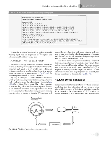
FUNCTION ¼ 30D * SINðTIME * 180DÞ For a closed loop steering manoeuvre a torque is applied
to the steering column, or a force to the steering rack if the
For the lane change manoeuvre described earlier the column is not modelled, that will vary during the simula-
measured steering wheel angles from a test vehicle can be tion so as to maintainthe vehicleon a predefined path. This
extracted and input as a set of XY pairs, which can requires a steering controller to process feedback of the
be interpolated using a cubic spline fit. A time history observeddeviationfromthepath(error)andtomodifythe
plot for the steering inputs is shown in Fig. 15.1-42 for torque accordingly as illustrated in Fig. 15.1-43.
lane change manoeuvres at 70 and 100 km/h.
By way of example the MSC.ADAMS statements
which apply the steering motion to the steering column to 15.1.13 Driver behaviour
body revolute joint and the spline data are shown in Table
15.1-3 for a 100 km/h lane change. The x values are points It becomes inevitable with any form of vehicle dynamics
in time and the y values are the steering inputs in degrees. modelling that the interaction of the operator with
In the absence of measured data it is possible to construct the vehicle is a source of both input and disturbance. In
an open loop single or double lane change manoeuvre using flight dynamics, the phenomenon of ‘PIO’ – pilot in-
a combination of nested arithmetic IF functions with duced oscillation – is widely known. This occurs when
Torque applied to
handwheel
Error
T Fn (error)
Fig. 15.1-43 Principle of a closed loop steering controller.
505