
Page 496 - Automotive Engineering Powertrain Chassis System and Vehicle Body
P. 496
CHAP TER 1 5. 1 Modelling and assembly of the full vehicle
Error Input
Reference Output
Plant
Gain
Feedback
Fig. 15.1-41 An open-loop system, in black, is a subset of a closed-loop system, in grey.
15.1.12.3 Steering inputs for vehicle When a closed-loop controller is added to the system,
handling manoeuvres its goal is to allow the input to the plant to be adjusted so
as to produce the desired output. The desired output is
The modelling of steering inputs suggests for the first referred to as the ‘reference’ state; a difference between
time some representation of the driver as part of the the actual output and the reference is referred to as an
full vehicle system model. Any system can be consid- ‘error’ state. The goal of the control system is to drive the
ered to consist of three elements – the ‘plant’ (the item error to zero.
to be controlled), the input to the plant and the output We can consider an example of a closed loop steering
from the plant (Fig. 15.1-41). Inputs to the system (i.e. input that requires a torque to be applied to the handwheel
handwheel inputs) are referred to as ‘open loop’ or or steering column such that the vehicle will follow
‘closed loop’. An open loop steering input requires a predetermined path during the simulation. A mechanism
a time dependent rotation to be applied to the part must be modelled to measure the deviation of the vehicle
representing a steering column or handwheel in the from the path and process this in a manner that feeds back
simulation model. In the absence of these bodies an to the appliedsteeringtorque. Asthe simulationprogresses
equivalent translational input can be applied to the joint the torque is constantly modified based on the observed
connecting a rack part to the vehicle body or chassis, path ofthevehicle andthedesiredtrajectory. Suchaninput
assuming a suspension linkage modelling approach has is referred to as closed loop since the response is observed
been used. Examples will be given here where the time and fed back to the input, thus closing the control loop.
dependent motion is based on a predetermined func- To return to the open-loop case, we can consider an
tion or equation to alter the steering inputs or a series example of an open loop manoeuvre for a steering input
of measured inputs from a vehicle on the proving where we want to ramp a steering input of 90 degrees
ground. between 1 and 1.5 seconds of simulation time. Using an
Any system can be considered to consist of three el- MSC.ADAMS solver statement the function applied to
ements – the ‘plant’ (the item to be controlled), the the steering motion would be:
input to the plant and the output from the plant
(Fig. 15.1-41). FUNCTION ¼ STEPðTIME; 1; 0; 1:5; 90DÞ
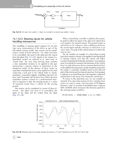
Fig. 15.1-42 Steering input for the lane change manoeuvre at 70 km/h (dashed line) and 100 km/h (solid line).
504