
Page 495 - Automotive Engineering Powertrain Chassis System and Vehicle Body
P. 495
Modelling and assembly of the full vehicle C HAPTER 15.1
coupler statements to link the rotation between the at the road wheels would vary as the vehicle rolls
steering column and each of the front wheel joints as and the road wheels move in bump and rebound.
shown in Fig. 15.1-38. (ii) For either wheel the ratio of toe out or toe in as
a ratio of left or right handwheel rotation would
15.1.12.2 Steering ratio not be exactly symmetric.
In order to implement the ratios used in the couplers Modelling the suspension with linkages will capture
shown in Fig. 15.1-38 linking the rotation of the steering these effects. Although this may influence the modelling
column with the steer change at the road wheels it is of low speed turning they have little effect for handling
necessary to know the steering ratio. At the start of manoeuvres with comparatively small steer motions.
a vehicle dynamics study the steering ratio can be With simpler vehicle models, not including suspension
a model design parameter. In the examples here a ratio of linkages, the ratio would need to be functionally de-
20 degrees of handwheel rotation to 1 degree of road pendent on the vertical movement of the suspension and
wheel steer is used. On some vehicles this may be lower direction of handwheel rotation if the behaviour is to be
and on trucks or commercial vehicles it may be higher. To modelled. It should also be noted that compliance in the
treat steering ratio as linear is a simplification of the sit- steering rack or rotational compliance in the steering
uation on a modern vehicle. For example, the steering column could be incorporated if the analysis dictates
ratio may vary between a higher value on centre to this.
a lower value towards the limits of rack travel or vice In the following example the geometric ratio between
versa. This would promote a feeling of stability for the rotation of the steering column and the travel of the
smaller handwheel movements at higher motorway rack is already known, so it is possible to apply a motion
speeds and assist lower speed car park manoeuvres. input at the rack to ground joint that is equivalent to
Using the multibody systems approach the steering handwheel rotations either side of the straight ahead
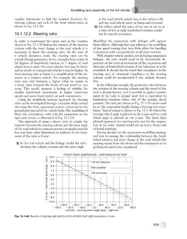
ratio can be investigated through a separate study carried position. The jack part shown in Fig. 15.1-39 can be used
out using the front suspension system connected to the to set the suspension height during a steering test simu-
ground part instead of the vehicle body. The modelling of lation. Typical output is shown in Fig. 15.1-40 where the
these two subsystems, with only the suspension on the steering wheel angle is plotted on the x-axis and the road
right side shown, is illustrated in Fig. 15.1-39. wheel angle is plotted on the y-axis. The three lines
The approach of using a direct ratio to couple the plotted represent the steering ratio test for the suspen-
rotation between the steering column and the steer angle sion in the static (initial model set up here), bump and
of the road wheels is common practice in simpler models rebound positions.
but may have other limitations in addition to the treat- Having decided on the suspension modelling strategy
ment of the ratio as linear: and how to manage the relationship between the hand-
wheel rotation and steer change at the road wheels the
(i) In the real vehicle and the linkage model the ratio steering inputs from the driver and the manoeuvre to be
between the column rotation and the steer angle performed need to be considered.
FRONT RIGHT SUSPENSION – STEERING RATIO TEST
Toe out – road wheel steer (deg) – toe in 2.0 Static position _______________
10.0
_ _ _ _ _ _ _ _
8.0
100 mm rebound
6.0
4.0
___ ___ ___ ___
100 mm bump
2.0
0.0
4.0
6.0
8.0
10.0
150.0 90.0 30.0 30.0 90.0 150.0
180.0 120.0 60.0 0.0 60.0 120.0 180.0
Left turn – steering wheel angle (deg) – right turn
Fig. 15.1-40 Results of steering ratio test for MSC.ADAMS front right suspension model.
503