
Page 493 - Automotive Engineering Powertrain Chassis System and Vehicle Body
P. 493
Modelling and assembly of the full vehicle C HAPTER 15.1
Steering motion
MOTION applied at joint
Steering column
part
Steering rack
REV COUPLER part
Revolute joint to
vehicle body
TRANS Translational joint
to vehicle body
Front
suspension
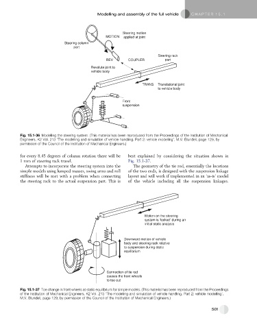
Fig. 15.1-36 Modelling the steering system. (This material has been reproduced from the Proceedings of the Institution of Mechanical
Engineers, K2 Vol. 213 ‘The modelling and simulation of vehicle handling. Part 2: vehicle modelling’, M.V. Blundell, page 129, by
permission of the Council of the Institution of Mechanical Engineers.)
for every 8.45 degrees of column rotation there will be best explained by considering the situation shown in
1 mm of steering rack travel. Fig. 15.1-37.
Attempts to incorporate the steering system into the The geometry of the tie rod, essentially the locations
simple models using lumped masses, swing arms and roll of the two ends, is designed with the suspension linkage
stiffness will be met with a problem when connecting layout and will work if implemented in an ‘as-is’ model
the steering rack to the actual suspension part. This is of the vehicle including all the suspension linkages.
Motion on the steering
system is ‘locked’ during an
initial static analysis
Downward motion of vehicle
body and steering rack relative
to suspension during static
equilibrium
Connection of tie rod
causes the front wheels
to toe out
Fig. 15.1-37 Toe change in front wheels at static equilibrium for simple models. (This material has been reproduced from the Proceedings
of the Institution of Mechanical Engineers, K2 Vol. 213 ‘The modelling and simulation of vehicle handling. Part 2: vehicle modelling’,
M.V. Blundell, page 129, by permission of the Council of the Institution of Mechanical Engineers.)
501