
Page 491 - Automotive Engineering Powertrain Chassis System and Vehicle Body
P. 491
Modelling and assembly of the full vehicle C HAPTER 15.1
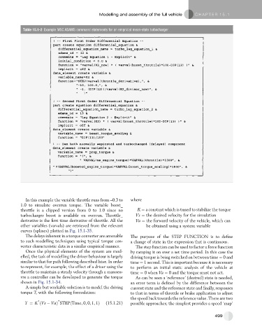
Table 15.1-2 Example MSC.ADAMS command statements for an empricial mean-state turbocharger
In this example the variable throttle runs from –0.3 to where
1.0 to simulate overrun torque. The variable boost_
throttle is a clipped version from 0 to 1.0 since no K ¼ a constant which is tuned to stabilize the torque
turbocharger boost is available on overrun. Throttle_ Vs ¼ the desired velocity for the simulation
derivative is the first time derivative of throttle. All the Va ¼ the forward velocity of the vehicle, which can
other variables (varvals) are retrieved from the relevant be obtained using a system variable
curves (splines) plotted in Fig. 15.1-35.
The delays inherent in a torque converter are amenable The purpose of the STEP FUNCTION is to define
to such modelling techniques using typical torque con- a change of state in the expression that is continuous.
verter characteristic data in a similar empirical manner. The step function can be used to factor a force function
Once the physical elements of the system are mod- by ramping it on over a set time period. In this case the
elled, the task of modelling the driver behaviour is largely driving torque is being switched on between time ¼ 0 and
similar to that for path following described later. In order time ¼ 1 second. This is important because it is necessary
to represent, for example, the effect of a driver using the to perform an initial static analysis of the vehicle at
throttle to maintain a steady velocity through a manoeu- time ¼ 0when Va ¼ 0 and the torque must not act.
vre a controller can be developed to generate the torque As can be seen a ‘reference’ (desired) state is needed,
shown in Fig. 15.1-34. an error term is defined by the difference between the
A simple but workable solution is to model the driving current state and the reference state and finally, responses
torque T, with the following formulation: to that in terms of throttle or brake application to adjust
the speed back towards the reference value. There are two
*
*
T ¼ K ðVs VaÞ STEPðTime; 0; 0; 1; 1Þ (15.1.21) possible approaches; the simplest provides a speed ‘map’
499