
Page 492 - Automotive Engineering Powertrain Chassis System and Vehicle Body
P. 492
CHAP TER 1 5. 1 Modelling and assembly of the full vehicle
450
400
350 Boost torque
NA torque curve
Torque (Nm) 250
300
Total torque
200
150
100
50
0
0 1000 2000 3000 4000 5000 6000 7000
Engine speed (rpm)
10
9
8 k1
Dimensionless 6
7
k2
5
4
3
2
1
0
0 1000 2000 3000 4000 5000 6000 7000
Engine speed (rpm)
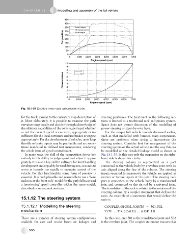
Fig. 15.1-35 Empricial mean-state turbocharger model.
for the track, similar to the curvature map description of steering gearboxes. The treatment in the following sec-
it. More elaborately, it is possible to examine the path tions is limited to a traditional rack and pinion system.
curvature map locally and decide (through a knowledge of Space does not permit discussion of the modelling of
the ultimate capabilities of the vehicle, perhaps) whether power steering or steer-by-wire here.
or not the current speed is excessive, appropriate or in- For the simple full vehicle models discussed earlier,
sufficient for the local curvature and use brakes or engine such as that modelled with lumped mass suspensions,
appropriately. For the development of vehicles, open loop there are problems when trying to incorporate the
throttle or brake inputs may be preferable and are some- steering system. Consider first the arrangement of the
times mandated in defined test manoeuvres, rendering steering system on the actual vehicle and the way this can
the whole issue of speed control moot. be modelled on the detailed linkage model as shown in
In many ways the skill of the competition driver lies Fig. 15.1-36. In this case only the suspension on the right-
entirely in this ability to judge speed and adjust it appro- hand side is shown for clarity.
priately. It is also a key skill to cultivate for limit handling The steering column is represented as a part
development and arguably for road driving too, so as not to connected to the vehicle body by a revolute joint with its
arrive at hazards too rapidly to maintain control of the axis aligned along the line of the column. The steering
vehicle. For this functionality, some form of preview is inputs required to manoeuvre the vehicle are applied as
essential. It is both plausible and reasonable to run a ‘here motion or torque inputs at this joint. The steering rack
and now at the front axle’ model for the path follower and part is connected to the vehicle body by a translational
a ‘previewing’ speed controller within the same model, joint and connected to the tie rod by a universal joint.
described in subsequent sections. The translation of the rack is related to the rotation of the
steering column by a coupler statement that defines the
ratio. An example of a statement that would define the
15.1.12 The steering system ratio is
15.1.12.1 Modelling the steering COUPLER=510502; JOINTS ¼ 501; 502;
mechanism TYPE ¼ T:R; SCALES ¼ 8:45D; 1:0
There are a number of steering system configurations In this case joint 501 is the translational joint and 502
available for cars and trucks based on linkages and is the revolute joint. The coupler statement ensures that
500