
Page 494 - Automotive Engineering Powertrain Chassis System and Vehicle Body
P. 494
CHAP TER 1 5. 1 Modelling and assembly of the full vehicle
COUPLER
COUPLER
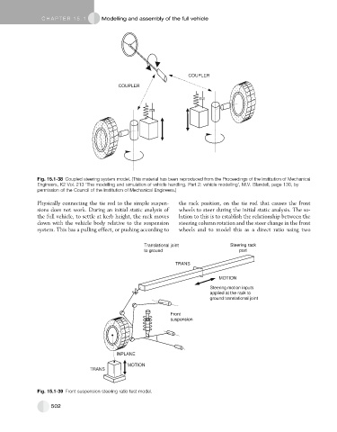
Fig. 15.1-38 Coupled steering system model. (This material has been reproduced from the Proceedings of the Institution of Mechanical
Engineers, K2 Vol. 213 ‘The modelling and simulation of vehicle handling. Part 2: vehicle modelling’, M.V. Blundell, page 130, by
permission of the Council of the Institution of Mechanical Engineers.)
Physically connecting the tie rod to the simple suspen- the rack position, on the tie rod that causes the front
sions does not work. During an initial static analysis of wheels to steer during the initial static analysis. The so-
the full vehicle, to settle at kerb height, the rack moves lution to this is to establish the relationship between the
down with the vehicle body relative to the suspension steering column rotation and the steer change in the front
system. This has a pulling effect, or pushing according to wheels and to model this as a direct ratio using two
Translational joint Steering rack
to ground part
TRANS
MOTION
Steering motion inputs
applied at the rack to
ground translational joint
Front
suspension
INPLANE
MOTION
TRANS
Fig. 15.1-39 Front suspension steering ratio test model.
502