
Page 603 - Automotive Engineering Powertrain Chassis System and Vehicle Body
P. 603
CHAP TER 1 8. 1 Design and material utilization
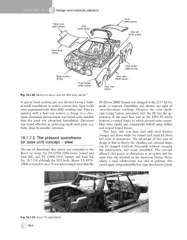
Trunk
(6000 series)
Hood outer
(6000 series) Roof
(6000 series)
Side sill
(6000 series)
Hood inner
(5052)
Rear fender
(6000 series)
Body skeleton Door outer
(5182) (6000 series)
Front fender
(6000 series) Door inner
(5052)
Fig. 18.1-23 Aluminium alloys used for NSX body panels. 9
A special hand welding gun was devised having a built- P6 (Rover 2000) bonnet was changed to the 2117 Al–Cu
in small transformer to reduce current loss. Spot welds grade to improve formability and obviate any signs of
were augmented with short MIG welding runs. Prior to ‘stretcher-strain’ markings. However, the most signifi-
painting with a four-coat system, a change to a chro- cant design feature associated with the P6 was the ap-
mate–chromium pretreatment was found more suitable pearance of the steel base unit in the 1964 P6 which
than the usual zinc phosphate formulation. Dacromet featured a central frame to which pressed outer assem-
was found effective in protecting small steel parts, e.g. blies were rigidly and consistently bolted using drilled
bolts, from bi-metallic corrosion. and tapped forged bosses.
This ‘base unit’ was then clad with steel fenders
(wings) and doors while the bonnet and trunk lid (boot
18.1.7.2 The pressed spaceframe lid) were in aluminium. The advantage of this type of
(or base unit) concept – steel design is that in theory the cladding and external shape
can be changed relatively frequently without changing
The use of aluminium skin panels was extended to the the substructure, and repair simplified. This concept
Rover car range, the P4 (1954–1964 doors, bonnet and allowed clad panels in aluminium as an option and the
boot lid), and P6 (1964–1976 bonnet and boot lid; same idea was adopted on the American Pontiac Fiero,
Fig. 18.1-24) although the SD1 body (Rover 3.5 1976– where a steel substructure was clad in polymer skin
1984) reverted to steel. It was interesting to note that the panels again using adjustable box type attachment points
Fig. 18.1-24 Rover P6 spaceframe.
614