
Page 611 - Automotive Engineering Powertrain Chassis System and Vehicle Body
P. 611
CHAP TER 1 8. 1 Design and material utilization
Fig. 18.1-33 Side view of Vanquish.
also presented to allow full vehicle testing of a new con- The final configuration of hydroformed components
cept rather than the body-only exercise with the ULSAB incorporated in the design is shown in Fig. 18.1-34 and
sedan, relying on FE modelling to predict performance. followed an extremely detailed study. It is worth men-
The Land Rover Freelander was chosen as the focus tioning that the normal procedure is to work to a con-
for this programme principally due to the maturity of the trolled pre-development plan whereby the features of
development programme for the vehicle and the design a new design are compared with the original, a cost-ef-
package which allowed application to either smaller or fective manufacturing route defined and rigorous testing
larger products. Although a Land Rover (hitherto body-on- of new components undertaken. The whole process is
chassis design), the body is of monocoque or unitary con- regulated with frequent timing reviews and concurrence
struction, and the incorporation of a rigid sectional product obtained before proceeding through successive ‘gate-
seemed a natural choice for a rugged off-road performer. ways’ or decision points. These pre-concept stages
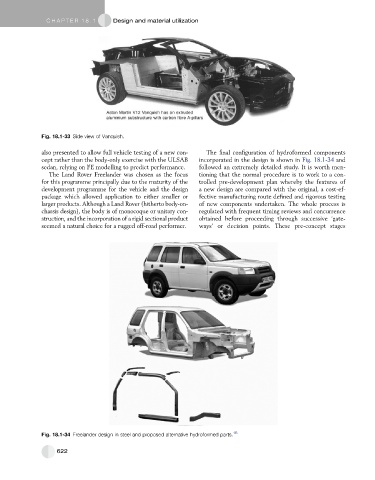
Fig. 18.1-34 Freelander design in steel and proposed alternative hydroformed parts. 16
622