
Page 612 - Automotive Engineering Powertrain Chassis System and Vehicle Body
P. 612
Design and material utilization C HAPTER 18.1
Body structure layer
Creative Application Focussing Confirmation
direction application of application
Component
Materials
System
Tooling & Forming
Assembly
Highlight main Generic Concept levels
issues application
Gateway 0 Apply to product
(a)
Package and performance attributes
Conventional Hydroformed radii
100% 84% 10 mm
Flange
16 mm
Circumference 447 mm Circumference 383 mm
Sectional benefits from hydroforming
Hydroformed
section Opportunity to employ
the additional package
Conventional space to increase the
press formed size of the section
section
Springback comparison
6 mm 20 mm
Ideal geometry Mild steel High strength steel
St 140 ZSt 260
Maximum deflection with hydroformed
components indicates 0.2 mm deflection
(b)
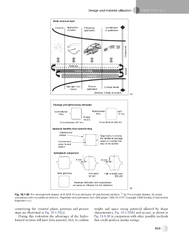
Fig. 18.1-35 Pre-development phases of ULSAB 40 and attributes of hydroformed sections. 16 (a) Pre-concept phases, (b) shape
comparison with conventional sections. (Reprinted with permission from SAE paper 1999-01-3181 Copyright 1999 Society of Automotive
Engineers Inc.)
constituting the ‘creative’ phase, gateways and process weight and space saving potential allowed by shape
steps are illustrated in Fig. 18.1-35(a). characteristics, Fig. 18.1-35(b) and second, as shown in
During this evaluation the advantages of the hydro- Fig. 18.1-36 in comparison with other possible methods
formed sections will have been assessed, first, to confirm that could produce similar savings.
623