
Page 613 - Automotive Engineering Powertrain Chassis System and Vehicle Body
P. 613
CHAP TER 1 8. 1 Design and material utilization
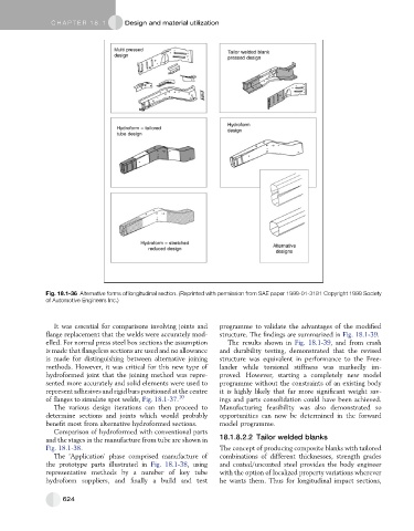
Fig. 18.1-36 Alternative forms of longitudinal section. (Reprinted with permission from SAE paper 1999-01-3181 Copyright 1999 Society
of Automotive Engineers Inc.)
It was essential for comparisons involving joints and programme to validate the advantages of the modified
flange replacement that the welds were accurately mod- structure. The findings are summarized in Fig. 18.1-39.
elled. For normal press steel box sections the assumption The results shown in Fig. 18.1-39, and from crash
is made that flangeless sections are used and no allowance and durability testing, demonstrated that the revised
is made for distinguishing between alternative joining structure was equivalent in performance to the Free-
methods. However, it was critical for this new type of lander while torsional stiffness was markedly im-
hydroformed joint that the joining method was repre- proved. However, starting a completely new model
sented more accurately and solid elements were used to programme without the constraints of an existing body
represent adhesives and rigid bars positioned at the centre it is highly likely that far more significant weight sav-
of flanges to simulate spot welds, Fig. 18.1-37. 10 ings and parts consolidation could have been achieved.
The various design iterations can then proceed to Manufacturing feasibility was also demonstrated so
determine sections and joints which would probably opportunities can now be determined in the forward
benefit most from alternative hydroformed sections. model programme.
Comparison of hydroformed with conventional parts
and the stages in the manufacture from tube are shown in 18.1.8.2.2 Tailor welded blanks
Fig. 18.1-38. The concept of producing composite blanks with tailored
The ‘Application’ phase comprised manufacture of combinations of different thicknesses, strength grades
the prototype parts illustrated in Fig. 18.1-38, using and coated/uncoated steel provides the body engineer
representative methods by a number of key tube with the option of localized property variations wherever
hydroform suppliers, and finally a build and test he wants them. Thus for longitudinal impact sections,
624