
Page 614 - Automotive Engineering Powertrain Chassis System and Vehicle Body
P. 614
Design and material utilization C HAPTER 18.1
Baseline practice Refined practice
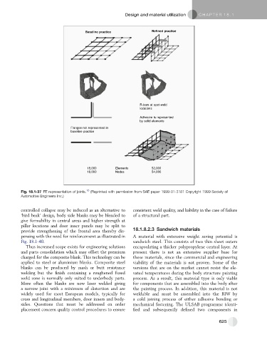
R-bars at spot-weld
locations
Adhesive is represented
by solid elements
Flanges not represented in
baseline practice
18,000 Elements 53,000
18,000 Nodes 54,000
Fig. 18.1-37 FE representation of joints. 16 (Reprinted with permission from SAE paper 1999-01-3181 Copyright 1999 Society of
Automotive Engineers Inc.)
controlled collapse may be induced as an alternative to consistent weld quality, and liability in the case of failure
‘bird beak’ design, body side blanks may be blended to of a structural part.
give formability in central areas and higher strength at
pillar locations and door inner panels may be split to
provide strengthening of the frontal area thereby dis- 18.1.8.2.3 Sandwich materials
pensing with the need for reinforcement as illustrated in A material with extensive weight saving potential is
Fig. 18.1-40. sandwich steel. This consists of two thin sheet outers
Thus increased scope exists for engineering solutions encapsulating a thicker polypropylene central layer. At
and parts consolidation which may offset the premium present there is not an extensive supplier base for
charged for the composite blank. This technology can be these materials, since the commercial and engineering
applied to steel or aluminium blanks. Composite steel viability of the materials is not proven. Some of the
blanks can be produced by mash or butt resistance versions that are on the market cannot resist the ele-
welding but the finish containing a roughened fused vated temperatures during the body structure painting
weld zone is normally only suited to underbody parts. process. As a result, this material type is only viable
More often the blanks are now laser welded giving for components that are assembled into the body after
a narrow joint with a minimum of distortion and are the painting process. In addition, this material is not
widely used for most European models, typically for weldable and must be assembled into the BIW by
cross and longitudinal members, door inners and body- a cold joining process of either adhesive bonding or
sides. Questions that must be addressed on order mechanical fastening. The ULSAB programme identi-
placement concern quality control procedures to ensure fied and subsequently defined two components in
625