Page 299 - Autonomous Mobile Robots
P. 299

286                                    Autonomous Mobile Robots

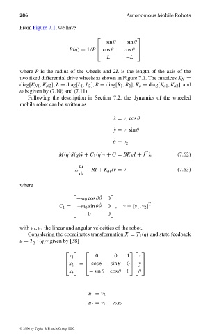
                                From Figure 7.1, we have

                                                                          
                                                              − sin θ  − sin θ
                                                  B(q) = 1/P  cos θ  cos θ 
                                                            
                                                                           
                                                                L      −L
                                where P is the radius of the wheels and 2L is the length of the axis of the
                                two fixed differential drive wheels as shown in Figure 7.1. The matrices K N =
                                diag[K N1 , K N2 ], L = diag[L 1 , L 2 ], R = diag[R 1 , R 2 ], K a = diag[K a1 , K a2 ], and
                                ω is given by (7.10) and (7.11).
                                   Following the description in Section 7.2, the dynamics of the wheeled
                                mobile robot can be written as


                                                                   ˙ x = v 1 cos θ
                                                                   ˙ y = v 1 sin θ


                                                                   ˙ θ = v 2
                                                                              T
                                               M(q)S(q)˙v + C 1 (q)v + G = BK N I + J λ   (7.62)
                                                      dI
                                                     L   + RI + K a µv = ν                (7.63)
                                                      dt

                                where

                                                                
                                                     −m 0 cos θ ˙ θ  0
                                                                               T
                                               C 1 = −m 0 sin θ ˙ θ  0 ,  v =[v 1 , v 2 ]
                                                                 
                                                    
                                                         0      0
                                with v 1 , v 2 the linear and angular velocities of the robot.
                                   Considering the coordinates transformation X = T 1 (q) and state feedback
                                u = T −1 (q)v given by [38]
                                     2
                                                                       
                                                  x 1       0      0   1    x
                                                 x 2 =  cos θ  sin θ  0 y
                                                  
                                                        
                                                                          
                                                  x 3     − sin θ  cos θ  0  θ

                                                         u 1 = v 2
                                                         u 2 = v 1 − v 2 x 2


                                 © 2006 by Taylor & Francis Group, LLC


                                FRANKL: “dk6033_c007” — 2006/3/31 — 16:43 — page 286 — #20
   294   295   296   297   298   299   300   301   302   303   304