
Page 356 - Battery Reference Book
P. 356
Terminal voltage-discharge time curves 31/5
12V 6V will have more of a slope, a lower end-voltage will
battery battery be necessary, and the ampere hours obtained per cycle
will be reduced.
- 12.0 - High-rate nickel-cadmium cells will deliver exceed-
L ingly high currents if they are discharged continu-
c P ll.0b ously under short-circuit conditions. Self-heating may
-
5 10.0 - pulses spaced to limit to a safe figure the temperatures
do irreparable damage. If the output is withdrawn in
g
C .- of a few critical areas in the cell, high currents can
9.0 - be utilized.
4.0Ll 2’C type to another, but in most cases internal metal
k The heat problems vary somewhat from one cell
8
I
I
I
I
strip tab connectors overheat and/or the electrolyte
1 2 4 6 10 20 4060 2 4 6 10 20 boils. General overheating is normally easy to prevent
b-min-z-h-1 because the outside temperature of the battery can be
Discharge time used to indicate when rest, for cooling, is required.
In terms of cut-off temperature during discharge, it is
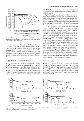
Figure 31.3 Discharge characteristic curves at 20°C for a Yuasa acceptable practice to keep the battery always below
sealed lead-acid bsattery. C = Ah rating at 20 h discharge rate to
1.75V/cell (Courtesy of Yuasa) 65°C. The overheated internal connectors are difficult
to detect. This form of overheating takes place in a
few seconds or less, and overall cell temperature may
when discharged at a 20 h rate to the final voltage of hardly be affected. It is thus advisable to withdraw no
1.75Vkell. The curves show currents drawn at dif- more ampere seconds per pulse, and to withdraw it
ferent discharge capacity rates at 20°C after a few at no greater average current per complete discharge,
charge/discharge cycles. It is clear from Figure 31.3 than recommended for the particular cell in question.
that the ampere hour capacities of the battery at a 20 h In special cases, where cooling of the cell or battery
rate expressed as standard values are smaller when the is likely to be poor (or unusually good), special tests
battery is subjected to discharge at greater than the should be run to check the important temperatures
20 h rate. before any duty cycle adjustment is made.
31.2.2 Nickel-cadmium batteries Cylindricul cell5
During discharge, the average voltage of a sealed Figure 3 1.4 shows discharge curves for several
nickel-cadmium battery is approximately 1.2 V/cell. cylindrical nickel-cadmium batteries of voltages
At normal discharge rates the characteristic is very between 6 and 14V and capacities between 0.5 and
nearly flat until the cell approaches complete dis- 4 Ah. Figures 3 1.5 and 3 1.6, respectively, compare
charge. The battery provides most of its energy above discharge curves for typical sealed nickel-cadmium
1 V/celP. If the cell is discharged with currents exceed- cylindrical cells made using mass electrodes and
ing the rated value, however, the voltage characteristic sintered electrodes.
- 16.8
I
8 6.5 15.6
m 0
” 14.4
5 6.0 -
>
5.5 t- \IQO~A \ -
4 13.2
t: 5.0 12.0
d 4.5 10.8
0 2 4 6 8 101214 0 2 4 6 8 101214
(a) Discharge time (h) (C) Discharge time (h)
- ..
5 7.0
6.5 2 15.6
m 6.0 14.4
P -
9 13.2
2 5.5 -
5.0 76 12.0
2 4.5 10.8
0 20 40 60 80 100 120 140 0 20 40 60 80 100 120 140
ib) Discharge time (rnin) (d) Discharge time (rnin)
Figure 31.4 Typical discharge curves at 20°C. Eveready sealed nickel-cadmium cylindrical batteries: (a,b) 6.0V, 0.5 Ah capacity,
(c,d) 14.4V, 4.OAh capacity (Courtesy of Union Carbide)