
Page 132 - Bebop to The Boolean Boogie An Unconventional Guide to Electronics Fundamentals, Components, and Processes
P. 132
Using Primitive Logic Functions to Build More Complex Functions 1 13
K5 Latch
reset NOR - 0 1
’-i 4, 1
9- set - -01
I
NOR
q = (reset I -01)
-q = (set I o$
0” 0”
(O* = Unstable State)
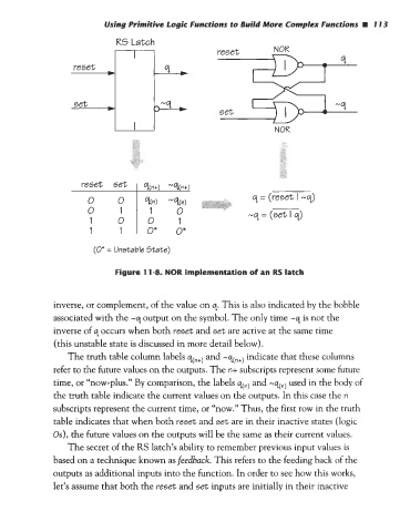
Figure 11-8. NOR implementation of an RS latch
inverse, or complement, of the value on q. This is also indicated by the bobble
associated with the -q output on the symbol. The only time -q is not the
inverse of q occurs when both reset and set are active at the same time
(this unstable state is discussed in more detail below).
The truth table column labels qn+) and -qn+) indicate that these columns
refer to the future values on the outputs. The n+ subscripts represent some future
time, or “now-plus.” By comparison, the labels q(n) and -qn) used in the body of
the truth table indicate the current values on the outputs. In this case the n
subscripts represent the current time, or “now.” Thus, the first row in the truth
table indicates that when both reset and set are in their inactive states (logic
Os), the future values on the outputs will be the same as their current values.
The secret of the RS latch‘s ability to remember previous input values is
based on a technique known as feedback. This refers to the feeding back of the
outputs as additional inputs into the function. In order to see how this works,
let’s assume that both the reset and set inputs are initially in their inactive