
Page 130 - Bebop to The Boolean Boogie An Unconventional Guide to Electronics Fundamentals, Components, and Processes
P. 130
Using Primitive Logic Functions to Build More Complex Functions 17 7
function’s enable is indicated by the bobble associated with this input on the
symbol and by the tilde character in its name, -enable. (Similar functions with
active-high enables are also commonly used in designs.)
The Z character in the truth table represents a state known as high-impedance,
in which the gate is not driving either of the standard 0 or 1 values. In fact, in
the high-impedance state the gate is effectively disconnected from its output.
Although Boolean algebra is not well equipped to represent the Z state, the
implementation of the tri-state buffer is relatively easy to understand. When
the -enable input is presented with a 1 (its inactive state), the output of the OR
gate is forced to 1 and the output of the NOR gate is forced to 0, thereby turn-
ing both the Tr, and Tr, transistors OFF, respectively. With both transistors
turned OFF, the output y is disconnected from Vp, and V,,, and is therefore in
the high-impedance state.
When the -enable input is presented with a O (its active state), the
outputs of the OR and NOR gates are determined by the value on the data
input. The circuit is arranged so that only one of the Tr, and Tr2 transistors can
be ON at any particular time. If the data input is presented with a 1, transistor
Tr, is turned ON, thereby connecting output y to V,, (which equates to logic I).
By comparison, if the data input
is presented with a 0, transistor
Tr, is turned ON, thereby
connecting output y to V,,
(which equates to logic 0).
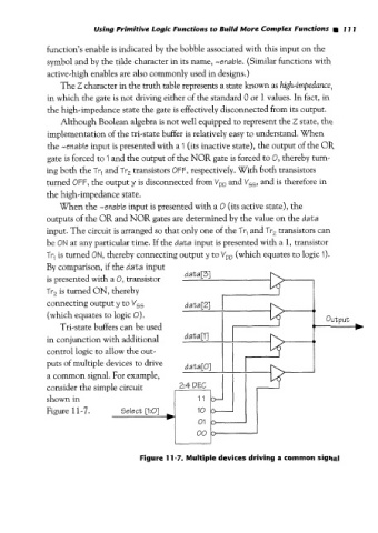
Tri-state buffers can be used
in conjunction with additional
control logic to aillow the out-
puts of multiple devices to drive data[O]
a common signal. For example,
consider the simple circuit
shown in
Figure 1 1-7.
Figure 11-7. Multiple devices driving a common signal