Page 41 - 02. Subyek Computer Aided Design - Beginner’s Guide to SOLIDWORKS 2019- Level 1 by Alejandro Reyes
P. 41

Part Modeling


                                                      2.2. - Now that we have made a new Part file, we can start modeling the part, and


                                                      the first thing we need to do is to make the extrusion for the base of the 'Housing'.


                                                      The first feature is usually one that other features can be added to or one that can


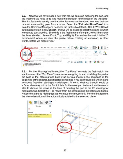
                                                      be used as a starting point for our model. Select the "Extruded Boss/Base" icon


                                                      from the Command Manager's Features tab (active by default).  SOLIDWORKS will


                                                      automatically start a new Sketch, and we will be asked to select the plane in which


                                                      we want to start working. Since this is the first feature of the part, we will be shown


                                                      the three standard planes (Front, Top, and Right). Remember the sketch is the 20


                                                      environment  where  we  draw  the  profile  before  creating  an  extrusion,  in  other


                                                      words, before we make it "30."


                                                                         L/DWQRKS                     File  Edit    View     Insert  Tools  Window  Help              Jt  D ... ~ ... - ...  ~ ...  ... ~ I  ~ {§} ...


                                                                                                                                                                                                                                        oc;!W      "J  r
                                                                                         Swept Boss  Base                                                  Swept Cut                                                      rap
                                                                                                                                                                                             )                                                     u          ~
                                                                                                                                                                                                                                           I
                                                                                                                                Hole                                           F  et    lmear                                        Reference  Curves         t  t D
                                                                                                                                                                                                                                                             ns  an
                                                                                         lofted Boss  Base         Extruded  Vi> IZard  Re  ol  ed         lofted Cut                  Pattern          Draft           lntersed      Geometry              1       3
                                                                                                                      Cut                   Cut

                                                                                         Boul'dary Boss/Base                                               Boundary tut          ...      ...           Shell           M  ror


                                                             Extrudes a sketch or selected sketch
                                                      1----1  contours in one or two directions to
                                                             create a solid feature.


                                                      2.3. - For the 'Housing' we'll select the "Top Plane" to create the first sketch. We


                                                      want to select the "Top Plane" because we are going to start modeling the part at


                                                      the  base  of the  'Housing' and  build  it  up  as was  shown  in  the sequence  at the


                                                      beginning of the chapter. Don't get too concerned if you can't figure out which plane


                                                      to choose first when starting to model a part. At worst, what you thought would be


                                                      a Front view may not be the front; this is for the most part irrelevant, as the user is


                                                      able to  choose  the views  at the time  of detailing  the  part  in  the 20 drawing for


                                                      manufacturing. Select the "Top Plane"from the screen using the left mouse button.


                                                      Notice the plane is highlighted as we move the mouse to it.  For the first feature,


                                                      the view orientation will be automatically rotated to the selected plane.


                                                                                         Extrude                         ®


                                                                       X


                                                                      Message

                                                                      Select a plane on which to sketch the
                                                                      feature cross-section.


                                                                                                                                                                                         ,  ,     I
                                                                                                                                                                                                  I
                                                                                                                                                                                                  I


                                                                                                                                0


                                                                                                                                                             27
   36   37   38   39   40   41   42   43   44   45   46