
Page 572 - 02. Subyek Computer Aided Design - Beginner’s Guide to SOLIDWORKS 2019- Level 1 by Alejandro Reyes
P. 572
Assembly Modeling
With Gears
L Origin ;..
~ ~ (f) Housing<1> (Machined« Default> _Display
~ ~ Side Cover<1> (Machined«Default> _Display~
~ ~ (-)Worm Gear Shaft< 1 > (Default<< Default> _D
~ ~ (-)Worm Gear Complete<2> (Default< <Defaul·
~ ~ (-) Offset Shaft Gear< 1 > (Default« Default> _Di
~Top Cover<1> (Default« Default> _Display Stat
~ i (-)socket head cap screw_ai<1> (HX-SHCS0.1:
~ i (-)socket head cap screw_ai<2> (HX-SHCS 0.1:
~ i (-)socket head cap screw_ai<3> (HX-SHCS0.1:
~ i (-) socket head cap screw_ai<4> (HX-SHCS 0.1:
~ i (-)socket head cap screw_ai<S> (HX-SHCS 0.2~
~ ..) (-) Offset Shaft< 1 > (Default)
~..)(-)Worm Gear<1> (Default)
~ @@ Mates
~ GljiJ MirrorComponent1
~ ~~ DerivedCirPattern1
~ GljiJ MirrorComponent2
< >
Configurat ions
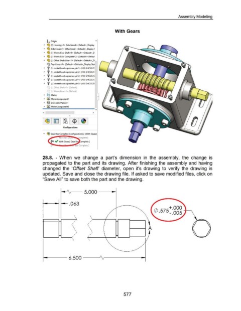
28.8. - When we change a part's dimension in the assembly, the change is
propagated to the part and its drawing. After finishing the assembly and having
changed the 'Offset Shaft' diameter, open it's drawing to verify the drawing is
updated. Save and close the drawing file. If asked to save modified files, click on
"Save All" to save both the part and the drawing.
I
\ \
\ \
/
~ / /
/ /
\ \
\ \
\ \ A
\ \
/ /
/ /
~
/ /
\
\
577