
Page 660 - 02. Subyek Computer Aided Design - Beginner’s Guide to SOLIDWORKS 2019- Level 1 by Alejandro Reyes
P. 660
Animation and Rendering
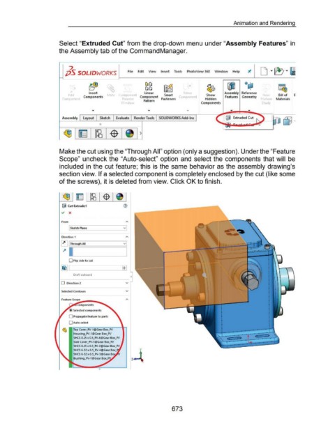
Select "Extruded Cut" from the drop-down menu under "Assembly Features" in
the Assembly tab of the Command Manager.
2 D T ~ T 61
jj5 SOLIDWORKS File Edit View Insert Tools PhotoView 360 Window Help
b~ ~ ~~ ~ ..:.t ~ ~ Qcj;l f!&,
~~
I
Insert linear r o e Assembly Reference
Ed1t Components ate Componer Component Smart omponen Show Features Geometry Ne Bill of E
Componer Pre 1e Pattern Fasteners Hidden lot1or Materials
\ mdo Components Study
Assembly Layout Sketch Evaluate Render Tools SOLIDWORKS Add-Ins IWJ Extruded Cut
0
)
Make the cut using the "Through All" option (only a suggestion). Under the "Feature
Scope" uncheck the "Auto-select" option and select the components that will be
included in the cut feature; this is the same behavior as the assembly drawing's
section view. If a selected component is completely enclosed by the cut (like some
of the screws), it is deleted from view. Click OK to finish.
iJ Cut-Extrude1
~ X
From
[ Sketch Plane v
Direction 1
~ [ Through All v
~ l .___l __ ______,
0 Flip side to cut
Draft outward
0 Direction 2 v
Selected Contours v
Feature Sco~pe-....-..... ........_
components
Selected components
0 Propagate feature to parts
0 Auto-select
~ Top Cover_PV-1 @Gear Box_PV
Housing_PV-1@Gear Box_PV
SHCS 0.25 x 0.5_PV-6@Gear Box_PV
Side Cover_PV-1 @Gear Box_PV
SHCS 0.25 x 0.5_PV-2@Gear Box_PV
y
SHCS 6-32 x 0.5_PV-4@Gear
z-t
Bushing_PV-1 @Gear
673