
Page 74 - 02. Subyek Computer Aided Design - Beginner’s Guide to SOLIDWORKS 2019- Level 1 by Alejandro Reyes
P. 74
Beginner's Guide to SOLIDWORKS 2019- Level I
To make the extrusion, switch to an isometric view using the View
Orientation tool bar and select the circle of the previously made sketch. Be aware
that now we are editing the part, we left the sketch editing environment when we
exit the sketch. After the sketch circle is selected with the "lnstant3D" active, click-
and-drag on the arrow that appears in it; this is the handle to extrude the sketch.
You will immediately see a dynamic ruler that will show the size of the extrusion as
you drag it. Make sure to extrude it 0.250". When you release the handle, a new
extrusion will be created. To modify this (or any other) extrusion, select the front
face of the extrusion and drag the handle to a new size.
You can control the size of the extrusion with more precision by dragging
the handle over the ruler's marks; this way the handle will snap to the
markers.
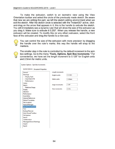
The smaller step in the ruler is controlled by the default increment in the spin
box settings. Go to the menu "Tools, Options, Spin Box Increments." For
convenience, we have set the length increment to 0.125" for English units
and 2.5mm for metric units.
System Options - Spin Box Increments
System Options Document Properties
General length increments
Drawings English units: I 0.1 25in
1 .... Display Style
1···· Area Hatch/ Fill Metric units: 12.50mm
L .. Performance
Colors
Angle increments: 1 1.00<>
Sketch
L. .. Relations/ Snaps
Time increments: I 0.10s
Display
Selection
Performance
Assemblies
External References
Default Templates
File locations
FeatureManager
Spin Box Increments
View
Backup/ Recover
Hole \1\fizard/T oolbox
File Explorer
Search
Collaboration
Messages/ Errors/Warnings
Import
Export
64