Page 247 - Biaxial Multiaxial Fatigue and Fracture
P. 247

Fatigue Analysis  of Multiaxially Loaded  Components with the FE-Postprocessor FEMFAT-MAX   23 1


                800
                700
                MR
                600

                500
              m
              4  400
              .- -
              c
              a
              5
              2  300
              -
              .!I
              w
              -
              0  "
              _I
                 20c
                 150
                   2     5   10'   2    s   105   2    5   106   2    5    107
                                           Fatigue life  to  crack  initiation N,  la E 0.25mm 1
             - A SibJrger
              Ref.:
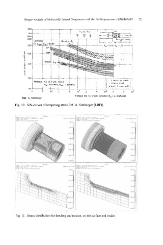
         Fig. 10.  S/N-curves of tempering steel (Ref. A. Simburger (LBF))


          Fig. 1 1.  Stress distribution for bending and torsion, on the surface and inside.
   242   243   244   245   246   247   248   249   250   251   252