
Page 249 - Biaxial Multiaxial Fatigue and Fracture
P. 249
Fatigue Analysis of Muitiaxially Loaded Components with the FE-Pospmcessor FEMFAT-MAX 233
A NEW METHOD TO TAKE INTO ACCOUNT PHASE SHIFTS
Integral methods have a disadvantage: They would deliver different results also for uniaxial
bending and torsional loading. But the numerical results are good and should not be affected.
Therefore we propose to change the S/N-curve in dependence of a multiaxiality parameter. This
parameter could be simply the phase shift. But in practice this is not a good choice, because a
phase shift can be defined only for monofrequentic signals. It should be possible to define such
a parameter which can be applied for stochastic signals too. A solution has been implemented
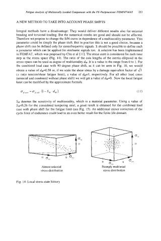
in FEMFAT, which was proposed by Chu et a1 [I 11. The stress state is considered for each time
step in the stress space (Fig. 14). The ratio of the axis lengths of the inertia ellipsoid in the
stress space can be used as degree of multiaxiality d~. It is a value in the range from 0 to 1. For
the combined load case with 90 degree phase shift, as it can be seen in Fig. 10, we would
obtain a value of dfi0.58 or, if we scale the shear stress by a damage equivalent factor of 6
(= ratio tensionkhear fatigue limit), a value of dpl, respectively. For all other load cases
(uniaxial and combined without phase shift) we will get a value of dp0. Now the local fatigue
limit can be modified by the approximate formula
SM denotes the sensitivity of multiaxiality, which is a material parameter. Using a value of
Sp0,26 for the considered tempering steel, a good result is obtained for the combined load
case with phase shift for the fatigue limit (see Fig. 15). An additional minor correction of the
cycle limit of endurance could lead to an even better result for the finite life domain.
, ... ..
. . .. .::
.*
. .. ..: ;, t.; . -- 0
- **
;::*,
...*. .
. ..*.>, +:*; *
Almost uniaxial Strongly multiaxial
stress-distribution stress-distribution
Fig. 14: Local stress state history