
Page 250 - Biaxial Multiaxial Fatigue and Fracture
P. 250
234 C. GAIER AND H. DANNBAUER
+Bending Test - -B - Bending Femfat
+Torsion Test - -e - Torsion Femfat
+Comb. 0" Test - - Comb. 0" Femfat
+Comb. 90" Test - 8 - Comb. 90" Femfat
500
- 450
n
r
o 400
s
= -
n
E 350
ul
E
3 - 300
x
rn
-I
250
--- .
1000 loo00 100OoO 1ooo0Oo 100ooooo
Number of cycles
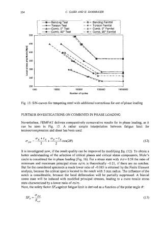
Fig. 15: S/N-curves for tempering steel with additional corrections for out of phase loading
FURTHER INVESTIGATIONS ON COMBINED IN PHASE LOADING
Nevertheless, FEMFAT delivers comparatively conservative results for in phase loading, as it
can be seen in Fig. 15. A rather simple interpolation between fatigue limit for
tensiodcompression and shear has been used:
It is investigated now, if the result quality can be improved by modifying Eq. (12). To obtain a
better understanding of the selection of critical planes and critical stress components, Mohr's
circle is considered for in phase loading (Fig. 16). For a stress state with da= 0.58 the ratio of
minimum and maximum principal stress 03/01 is theoretically -0.21, if there are no notches.
But for the considered specimen a much lower ratio of 4.085 is obtained by the Finite Element
analysis, because the critical spot is located in the notch with 5 mm radius. The influence of the
notch is considerable, because the local deformation will be partially suppressed. A biaxial
stress state will be induced with modified principal stresses, leading to a more tensile stress
state characterized by a lower ratio of 03/01.
Next, the safety factor SFo against fatigue limit is derived as a function of the polar angle 6 :