
Page 267 - Biaxial Multiaxial Fatigue and Fracture
P. 267
The Multiaxial Fatigue Strength of Specimens Containing Small Defects 25 1
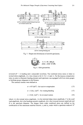
(a) For combined axiaVtorsiona1 load test
or reversed torsion test (b) For tension-compression test and
combined axialltorsional load test
under do = 112
( 5 0 50
< -'- 140 -'- h
(c) For reversed torsion test
(d) For rotating bending test
Fig. 5. Shapes and dimensions of smooth specimens.
Fig. 6. Hole geometries.
reversed (R = -1) loading and a sinusoidal waveform. The combined stress ratios of shear to
normal stress amplitude, do, were chosen to be 0, 1/2,1,2 and oc) . For the tension-compression
tests, in order to eliminate bending stresses each specimen was equipped with four strain gauges
to facilitate proper alignment in the fixtures.
The nominal stresses were defined as
o = ~P/(I~D') for tension-compression (12)
CT = 32M, /(a3) rotating bending (13)
for
T = 16M, /(zD3) for reversed torsion (14)
where CT is the normal stress amplitude, z is the torsional shear stress amplitude, P is the axial
load amplitude, Mb is the bending moment amplitude, Mt is the torsional moment amplitude and
D is the specimen diameter. The fatigue limits under combined stress are defined as the
combination of the maximum nominal stresses, ra and 0, under which a specimen endured 10'