
Page 323 - Biaxial Multiaxial Fatigue and Fracture
P. 323
Influence of Defects on Fatigue Life of Aluminium Pressure Diecastings 307
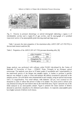
Fig. 4. Porosity in pressure diecastings: a) optical micrograph indicating a region A of
interdendritic cavities and a region B of gas cavities, and b) macrograph of a polished
transversal section of an unacceptable pedal showing small and large pores.
Table 2 presents the main properties of the aluminium alloy AS9U3 (NF A57-702/703) in
the non heat-treated condition [8].
Table 2. Properties of the AS9U3 (NF A57-703) pressure diecasting alloy [SI.
I ~~oy~roperties Value I
I
cr (MPa) I 200
Elongation (%\ I 0.5-1.5
I Density(g/cc) I 2.8 I
Image analysis was performed with software called PAQUI (developed by the Centre of
Materials of University of Porto - CEMUP, Porto, Portugal) in an Olympus optical
microscope. The analyses were done in 10 brake pedals (5 acceptable and 5 unacceptable), in
the transversal section of the fatigue test samples region. A routine to perform a specific
analysis was defined in order to count and measure the defects (considered spherical) in the
samples section. 50 to 80 fields were characterised in each sample, using an optical microscope
with a 5x magnification. Very small defects, with diameter <50 pm, were counted but not
measured in order to reduce the amount of data to be treated. The mean reletive defects area
was obtained dividing the total defects area by the total fields area. Figure 5 presents one of the
fields analysed in an unacceptable sample. Figure 6 presents the mean number of defects
detected in each field, classified in five diameter (pm) classes. As expected, unacceptable parts
have higher amount of defects in all classes.