
Page 380 - Biaxial Multiaxial Fatigue and Fracture
P. 380
364 M. FOhTE ET AL.
Magnitude of AK* and K*- to a crack advance
Schmidt and Paris [45] were the first who plotted AK& and K-, in terms of the R-ratio
identified the two thresholds and interpreted this result with the crack closure concept. Later,
Doker and Marci [46] plotted AKth vs K,, to identi@ the two critical thresholds (AK'th and
K*-) as minimum condition for crack growth. It was recognised that AK and K- provide
two crack tip driving forces [47]. These two driving forces are required to specify the loads
unambiguously. In the fatigue literature, the load ratio, R, is normally specified in addition to
AK as the second parameter. But this is considered as a not appropriate load parameter since
one does not have a critical R-ratio below which crack growth does not occur. Since crack
closure contributions are considered as small or negligible for most cases, AK and K- alone
can adequately explain the material response to fatigue loading, and crack closure is
unnecessary.
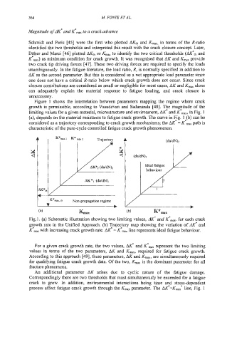
Figure 1 shows the interrelation between parameters mapping the regime where crack
growth is permissible, according to Vasud6van and Sadananda [48]. 'l?x maetude of the
limiting values for a given material, microstructure and environment, AK and K -, in Fig. 1
(a), depends on the material resistance to fatigue crack growth. The curve in eg. le@) can be
considered as a trajectory corresponding to crack growth mechanisms; the AK = K path is
characteristic of the pure-cycle controlled fatigue crack growth phenomenon.
dK*U
L .........
K*-x. th Non-propagation regime
b
(4 Lax (b) K*max
Fig.1. (a) Schematic illustration showing two limiting values, dK' and KOrnm for each crack
growth rate in the Unified Approach. (b) Trajectory map showing the variation of AK* and
K*- with increasing crack growth rate. AK* = KOm, line represents ideal fatigue behaviour.
For a given crack growth rate, the two values, hlyI and K'- represent the two limiting
values in terms of the two parameters, AK and K-, required for fatigue crack growth.
According to this approach [49], these parameters, AK and K,,, are simultaneously required
for qualifying fatigue crack growth data. Of the two, Kmax is the dominant parameter for all
fracture phenomena.
An additional parameter AK arises due to cyclic nature of the fatigue damage.
Correspondingly there are two thresholds that must simultaneously be exceeded for a fatigue
crack to grow. In addition, environmental interactions being time atd strefs-dependent
process affect fatigue crack growth through the Kmm parameter. The AK =K,, line, Fig. 1