
Page 41 - Biaxial Multiaxial Fatigue and Fracture
P. 41
26 G. SAVAIDIS ET AL.
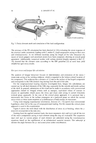
Detail of weld modelling
Fig. 5. Finite element mesh and simulation of the load configuration
The accuracy of the FE calculation has been checked in [IO] evaluating the strain response of
the structure under monotonic loading with F, and/or Fy (load components acting on their own
and simultaneously). At six different locations along the length of the tube measured (by
means of strain gauges) and calculated strains have been compared, showing an overall good
agreement. Additionally, numerical studies with various element lengths reported in Ref. [7,
101 showed that the element sizes according to the IIW guideline [I] as used here yield
reliable hot spot stress results.
Hot spot stress and fatigue life calculation
The analysis of fatigue behaviour focuses on determination and estimation of the stress /
strain state acting at the welding undercut, which is regarded as the failure-critical location of
the component. This undercut has a distance of 12 mm to the surface of the forged component
and corresponds to the fifth element ring starting from the end of the tube.
For the nonproportional loading situation investigated here, fatigue life calculations are
carried out for all shell elements of the fifth ring, separately for the outside and inside surface
of the shell. In general, calculations of this kind can be made in accordance with conventional
approaches (based on integral criteria such as energies, equivalent values of stresses or
strains) or approaches which assess the stress and strain state acting in certain directions
(critical plane approach). In the case of the critical plane approach, it is assumed that a
microcrack that forms at the surface propagates on a preferred plane on which the normal
stress-strain or shear strain response or a combination of both reaches its maximum.
Using wide-ranging experimental information, Sonsino [ 1 1, 121 reports that conventional
hypotheses often fail in the case of nonproportional loading. For this reason the critical plane
approach is used in this examination.
Figure 6 shows the weld detail with the distribution of stress o, at bending, where the y-
direction corresponds to the tube axis.
Starting from the applied nominal loads, the stress sequences o,(l) and g(t) and all the rest
of the stress components acting at each element along the ring are evaluated. The sequences
odt) and zdt) in various planes of each element are calculated using the transformation
equations based on the equilibrium of an infinitesimal material element. The subscript
denotes the angle between the zy- and actual plane under consideration.