
Page 504 - Biaxial Multiaxial Fatigue and Fracture
P. 504
488 G, SHATIL AND h! ERSOY
EXPERIMENTAL RESULTS
Experimental development
The testing programme employed anticlastic bending rhombic specimens similar to those
proposed by Zamrik and Davis [21]. The biaxiality of stress is obtained in the centre of the
specimen by applying an anti-symmetric bending moment at the four comers of the specimen.
Several specimens with different geometries were tested, and the dimension of the specimen
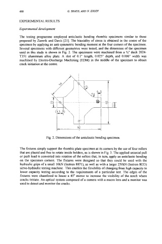
used in this study is shown in Fig. 2. The specimens were machined from a %I' thick 2024-
T351 aluminium alloy plate. A slot of 0.1" length, 0.025" depth, and 0.006" width was
machined by Electro-Discharge Machining (EDM) in the middle of the specimen to obtain
crack initiation at the centre.
Fig. 2. Dimensions of the anticlastic bending specimen.
The fixtures simply support the rhombic plate specimen at its comers by the use of four rollers
that are placed and free to rotate inside holders, as is shown in Fig. 3. The applied uniaxial pull
or push load is converted into rotation of the rollers that, in tum, apply an anticlastic bending
on the specimen comers. The fixtures were designed so that they could be used with the
hydraulic grips of a small lOkN (Instron 8871), as well as with a larger 250kN (Instron 8033)
servo-hydraulic testing machine. This enables the flexibility of changing from high capacity to
lower capacity testing according to the requirements of a particular test. The edges of the
fixtures were chamfered to house a 45" mirror to increase the visibility of the notch where
cracks initiate. An optical system composed of a camera with a macro lens and a monitor was
used to detect and monitor the cracks.