Page 152 - Bio Engineering Approaches to Cancer Diagnosis and Treatment
P. 152

150    CHAPTER 6  Laser-assisted cancer treatment


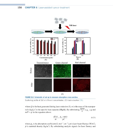
                         FIGURE 6.6  Schematic of set up to measure absorption cross-section.
                         Scattering profile of (GO at different concentration, (C) black absorber [75].


                         where Q is the heat generated during laser emission (J), m is the mass of the nanopar-
                                                                                /
 (J/kg K)
                                                                                        ϕ
 dQ/dtV=µa ×            ticle (kg)], C is the specific heat capacity (J/kgK). By substituting  dQ dt  =  µ ×  and
                                                                                     a
                           /
 m/V=ρ                   mV  =  ρ in the equation above:                       V
                                                    dT t ()  =  µ × ()                  (6.21)
                                                              ϕ t
                                                           a
 dT(t)dt=µa ×(t)ρC                                  dt     ρC
                                                                −1
                                                                                          2
                                                            −1
 µa                     where µ  is the absorption coefficient (L mol  cm ),  ϕ is laser beam fluency (W/m ),
                               a
                                               3
 ρ                       ρ is material density (kg/m ). By substituting analytic signals for laser fluency and
   147   148   149   150   151   152   153   154   155   156   157