
Page 113 - Biomedical Engineering and Design Handbook Volume 1, Fundamentals
P. 113
90 BIOMECHANICS OF THE HUMAN BODY
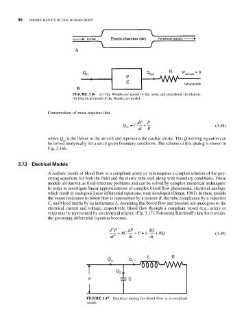
FIGURE 3.16 (a) The Windkessel model of the aorta and peripheral circulation.
(b) Electrical model of the Windkessel model.
Conservation of mass requires that
dP P
Q = C + (3.48)
in
dt R
where Q is the inflow to the air-cell and represents the cardiac stroke. This governing equation can
in
be solved analytically for a set of given boundary conditions. The scheme of this analog is shown in
Fig. 3.16b.
3.7.3 Electrical Models
A realistic model of blood flow in a compliant artery or vein requires a coupled solution of the gov-
erning equations for both the fluid and the elastic tube wall along with boundary conditions. These
models are known as fluid-structure problems and can be solved by complex numerical techniques.
In order to investigate linear approximations of complex blood flow phenomena, electrical analogs,
which result in analogous linear differential equations, were developed (Dinnar, 1981). In these models
the vessel resistance to blood flow is represented by a resistor R, the tube compliance by a capacitor
C, and blood inertia by an inductance L. Assuming that blood flow and pressure are analogous to the
electrical current and voltage, respectively, blood flow through a compliant vessel (e.g., artery or
vein) may be represented by an electrical scheme (Fig. 3.17). Following Kirchhoff’s law for currents,
the governing differential equation becomes
2
dP + RC dP + P = L dQ + RQ
dt 2 dt dt (3.49)
FIGURE 3.17 Electrical analog for blood flow in a compliant
vessel.