Page 127 - Biomedical Engineering and Design Handbook Volume 1, Fundamentals
P. 127

104  BIOMECHANICS OF THE HUMAN BODY

                       P = P , P = P , P = P , and Q  = F. As downstream pressure P is decreased and upstream pressure P
                        a  u  A  ext  v  d                          d                         u
                       is kept fixed, the flow increases until the internal pressure of the tube drops somewhat below the exter-
                       nal pressure P . Then the tube partially collapses, decreasing in cross-sectional area according to its
                                 ext
                       pressure-area or “tube law” relationship A(P), shown in Fig. 4.11b. As P is further decreased, the tube
                                                                         d
                       reduces its cross-sectional area while the average velocity of the flow increases. However, their product,
                       the volumetric flow rate F, does not increase as shown in Fig. 4.11c. A simplified understanding of this
                       behavior may be seen from the conservation of momentum equation for the flow, a Bernoulli equation,
                       where the average fluid velocity U is defined as the ratio of flow to cross-sectional area, U = F/A, all of
                       the terms pressure dependent.
                                                                  2
                                                             FP ⎞
                                                          1  ⎛ ()
                                                   P =  P + ρ ⎜  ⎟                         (4.4)
                                                   res
                                                              AP ⎠
                                                          2  ⎝ ()
                       where P  = pressure in a far upstream reservoir where
                             res
                                fluid velocity is negligibly small
                             r = fluid density
                       P  is the alveolar air pressure, for example, when applied to limitation of air flow discussed below.
                        res
                       Taking the derivative of Eq. (4.4) with respect to P and setting the criterion for flow limitation as
                       dF/dP = 0 gives
                                                           12     12
                                                            /
                                                                   /
                                                     ⎛  AdP⎞   ⎛  E⎞
                                                 U =         =                             (4.5)
                                                   c  ⎜ ⎝ ρ  dA⎠ ⎟  ⎜ ⎟
                                                               ⎝ ⎠
                                                                ρ
                       where E is the specific elastance of the tube. The quantity (E/r) 1/2  is the “wave speed” of small pres-
                       sure disturbances in a fluid-filled flexible tube, and flow limitation occurs when the local fluid speed
                       equals the local wave speed. At that point, pressure information can no longer propagate upstream,
                       since waves carrying the new pressure information are all swept downstream.
                         The overall effect of nonuniform ventilation and perfusion is that both decrease as one progresses
                       vertically upward in the upright lung. But perfusion decreases more rapidly so that the dimen-

                       sionless ratio of ventilation to perfusion,VQ /, decreases upward, and can vary from approximately
                                                      A
                                                             36
                       0.5 at the lung’s bottom to 3 or more at the lung’s top. Extremes of this ratio are ventilated regions

                       with no blood flow, called dead space, where VQ /  Æ•, and perfused regions with no ventilation,
                                                         A

                       called shunt, where VQ /  Æ0.
                                      A
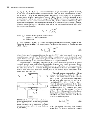
                                                              The steady-state gas concentrations within an
                                                            alveolus reflect the balance of inflow to outflow, as
                                                            shown in the control volumes (dashed lines) of
                                                            Fig. 4.12. For CO in the alveolar space, net inflow
                                                                        2
                                                            by perfusion must equal the net outflow by


                                                            ventilation,QC (  − C  ) =  V C (  − C  )
                                                                                   A
                                                                       v CO 2  c CO 2  A CO 2  inco 2
                                                            where  C indicates concentration. In the tissue
                                                            compartment, the CO production rate from
                                                                             2
                                                            cellular metabolism,V    ,  is balanced by net inflow
                                                                           CO 2
                                                            versus outflow in the tissues; i.e.,V CO 2  =

                                                            QC    − C  )  Noting that C  ª 0 and com-
                                                             (
                                                               v CO 2  c CO 2     inco 2
                                                            bining the two equations, while converting con-
                                                            centrations to partial pressures, leads to the
                                                            alveolar ventilation equation
                       FIGURE 4.12  Schematic for ventilation and perfusion in     V   CO 2
                       the lung and tissues. Dashed line indicates control volume  V = 863.  (4.6)
                                                                       A
                       for mass balance. Assume instantaneous and homogenous  P A  CO 2
                       mixing. Subscripts indicate gas concentrations for systemic
                       (s) or pulmonary (p) end capillary C , venous C , alveolar  where the constant 8.63 comes from the units
                                            c
                                                   v
                       C , and arterial C .
                        A        a                          conversion.  The inverse relationship between
   122   123   124   125   126   127   128   129   130   131   132