
Page 382 - Boiler_Operators_Handbook,_Second_Edition
P. 382
Controls 367
very limited. That’s probably more than you want to know
The control signal range is representative of the about control labels but you will find that your under-
value of the measured parameter, the process variable. standing of them will help you get answers to inquiries
You can measure the control signal and, knowing the about other control systems. Talk the talk and everyone
range of the transmitter, determine the actual value of thinks you’re an expert. Understand the talk, and you
the process variable. A simple example would be a loop are. Now lets talk actual controls and what they do.
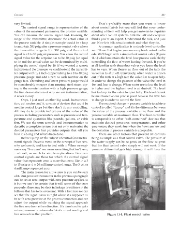
to maintain 200 psig after a pressure control valve where A common application is a simple level controller
the transmitter range is 0 to 300 psig and the control and I’ll use that to give you an example of control meth-
signal is a 0 to 30 psig air pressure. You know the control ods. We’ll begin with a simple float control valve (Figure
signal value for the setpoint has to be 20 psig (or equal 11-1) which maintains the level (our process variable) by
to it) and the actual value can be determined by multi- controlling the flow of water leaving the tank. If you’re
plying the control signal by 10. If we wanted a remote at all familiar with these float valves you know the level
indication of the pressure we could extend the transmit- has to vary. When there’s no flow out of the tank the
ter output with 1/4 inch copper tubing to a 0 to 30 psig valve has to shut off. Conversely, when water is drawn
pressure gauge and add a zero to each number on the out of the tank at a high rate the valve has to open fully.
gauge face. The tubing and lower pressure gauge would In order to change the position of the valve the level in
be considerably cheaper than running steel steam pip- the tank has to change. When water use is low the level
ing to the remote location with a high pressure gauge; is higher and the highest level is at shut-off. The level
the first demonstration of why we use instrumentation, has to drop for the valve to open fully. The level cannot
it saves money. be maintained at one precise point because the level has
Oops, I just used another big word. Instrumenta- to change in order to control the flow.
tion, as I understand it, consists of devices that could be The required change in process variable to achieve
used in control loops but they don’t do any controlling. control is called “droop” and it’s the difference between
All they do is provide indications of the value of the the value of the process variable at no flow and the
process including parameters such as pressure and tem- process variable at maximum flow. The float controller
perature and quantities like pounds, gallons, or cubic is comparable to other “self-contained” devices that
feet. We use the term controls and instrumentation to maintain desired pressures, temperatures, and other
describe a complete system that not only maintains the parameters; they work fine when the flows are low and
desired parameters but provides outputs that tell you the deviation in process variable is acceptable.
how it’s doing and what’s been done. There are other factors that prevent all controls
Before I jump off the subject of control (and instru- being as simple as a float control valve. The pressure of
ment) signals I have to mention the concept of live zero, the water supply can be so great, or the flow so great
why we have it, and how to deal with it. When we engi- that the float control valve simply will not work. If the
neers say “live zero” we mean something that isn’t zero; pressure differential gets high enough it will force the
…oh well, so much for simple explanations. Live zero
control signals are those for which the control signal
value that represents zero is more than zero; like in a 3
to 15 psig or 4 to 20 milliamp control range. The 3 psi or
4 milliamps represent zero.
The main reason for a live zero is you can be sure
of it. Our pressure transmitter in the previous paragraph
can be set at zero output with zero pressure applied to
it but we can’t be certain that it will come off that zero
properly; there may be slack in linkage or stiffness in the
bellows that has to be overcome. With a live zero we can
see that the signal value is right where it’s supposed to
be with zero pressure at the process connection and can
adjust the output while watching the signal approach
the live zero from either direction. It’s darn hard to get a
minus pressure or minus electrical current reading and
live zero solves that problem. Figure 11-1. Float control valve