
Page 383 - Boiler_Operators_Handbook,_Second_Edition
P. 383
368 Boiler Operator’s Handbook
valve open regardless of the position of the float. The high differential. You’ll probably never see anything
system in Figure 11-1 is obviously operating with very exactly like this type of controller (Figure 11-2 which is
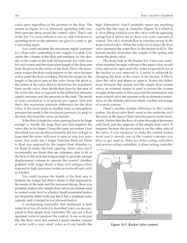
little pressure drop across the control valve. That’s one a valve filling a bucket over the valve with an opposing
of the few I’ve seen without a wire or cable led down to spring) but it allows me to show you some concepts of
operating level so the operator can give it a yank to get control. The valve controls flow to a bucket on top of the
it operating again. main control valve. When the water level drops the float
You could calculate the maximum supply pressure valve increases the water flow to the bucket to fill it. The
for a float valve controlling water supply to a tank. Cal- heavier bucket overcomes the weight of the spring and
culate the volume of the float and multiply by the den- closes the drain valve.
sity of the water in the tank (62.4 pounds per cubic foot The drain hole in the bucket lets water out, some-
for cold water) and the equivalent length of the float arm what essential because without it the main valve would
from the pivot to the center of the float. That’s the maxi- close and never open until the water evaporated out of
mum torque the float could impose on the valve because the bucket or you removed it. Control is achieved by
at that point the float is sinking. Divide the torque by the changing the level of the water in the bucket; it fills to
length of the pivot arm on the valve (from the pivot to close the valve and drains to open it. Notice the differ-
the center of the valve disc) to determine the maximum ences between this system and the simple float control
force on the valve, then divide that force by the area of valve; an external source is used to power the system
the valve disc that is exposed to the difference between (weight of the water in this case) and the transmitter and
supply pressure and the pressure in the tank. The result main control valve are separate with no dramatic restric-
of your calculation is in pounds per square inch and tions on the distance between them, another advantage
that’s the maximum pressure difference for the float of control systems.
valve. If the drain leads to another tank at atmospheric There’s another notable difference in this control
pressure the result is the maximum pressure (in psig) in system, the float valve that’s used as the controller isn’t
the tank, the most the valve can handle. the same as the typical float valve because it works back-
If the flow is high the valve opening has to be large wards. Notice that the flow of water through it decreases
enough to handle the large flow and that requires the with level, just the opposite of the simple float valve. It
valve disc to be larger. Using the same procedure I just happens because the pivot point is on the other side of
described you can see that eventually the disc will get so the valve. It was necessary to make the control system
large that the water will force it open at very low pres- work and it reveals one of the control concepts you
sures. You could use a larger float but there are limits have to get used to, there are direct acting controllers
to float size imposed by the largest float chamber or, and reverse acting controllers. A direct acting controller
for floats in tanks, the tank opening. That’s why you’ll
occasionally see floats that are cylinders, able to fit in
the hole in the tank but long enough to provide enough
displacement volume to operate the control. Another
problem with larger floats is they will collapse when
exposed to high pressures inside an enclosed tank such
as a boiler.
You could increase the length of the float arm to
increase the torque but there’s limits to that imposed by
the inside of the tank and the increased droop. Now you
probably realize why simple float valves are seldom used
to control water level in a boiler. Small residential boilers
are frequently fitted with one but it has a minimal water
capacity and is limited to low pressure boilers.
A modulating controller that maintains a tank
water level (on off control is described later) can be com-
pared to that simple float controller. We can use a float
operated valve to produce the control. It can work just
like the float valve but control a much smaller volume
of water with a very small valve so it can handle the Figure 11-2. Bucket valve control