
Page 385 - Boiler_Operators_Handbook,_Second_Edition
P. 385
370 Boiler Operator’s Handbook
following the nozzle. When the level falls the nozzle is would introduce an error, the output would be lower
pressed against the baffle so the pressure increases and than it should be.
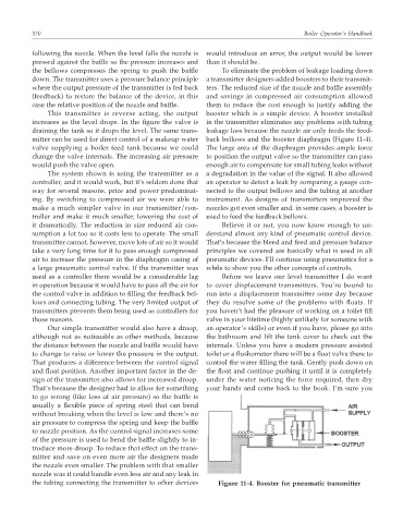
the bellows compresses the spring to push the baffle To eliminate the problem of leakage loading down
down. The transmitter uses a pressure balance principle a transmitter designers added boosters to their transmit-
where the output pressure of the transmitter is fed back ters. The reduced size of the nozzle and baffle assembly
(feedback) to restore the balance of the device, in this and savings in compressed air consumption allowed
case the relative position of the nozzle and baffle. them to reduce the cost enough to justify adding the
This transmitter is reverse acting, the output booster which is a simple device. A booster installed
increases as the level drops. In the figure the valve is in the transmitter eliminates any problems with tubing
draining the tank so it drops the level. The same trans- leakage loss because the nozzle air only feeds the feed-
mitter can be used for direct control of a makeup water back bellows and the booster diaphragm (Figure 11-4).
valve supplying a boiler feed tank because we could The large area of the diaphragm provides ample force
change the valve internals. The increasing air pressure to position the output valve so the transmitter can pass
would push the valve open. enough air to compensate for small tubing leaks without
The system shown is using the transmitter as a a degradation in the value of the signal. It also allowed
controller, and it would work, but it’s seldom done that an operator to detect a leak by comparing a gauge con-
way for several reasons, price and power predominat- nected to the output bellows and the tubing at another
ing. By switching to compressed air we were able to instrument. As designs of transmitters improved the
make a much simpler valve in our transmitter/con- nozzles got even smaller and, in some cases, a booster is
troller and make it much smaller, lowering the cost of used to feed the feedback bellows.
it dramatically. The reduction in size reduced air con- Believe it or not, you now know enough to un-
sumption a lot too so it costs less to operate. The small derstand almost any kind of pneumatic control device.
transmitter cannot, however, move lots of air so it would That’s because the bleed and feed and pressure balance
take a very long time for it to pass enough compressed principles we covered are basically what is used in all
air to increase the pressure in the diaphragm casing of pneumatic devices. I’ll continue using pneumatics for a
a large pneumatic control valve. If the transmitter was while to show you the other concepts of controls.
used as a controller there would be a considerable lag Before we leave our level transmitter I do want
in operation because it would have to pass all the air for to cover displacement transmitters. You’re bound to
the control valve in addition to filling the feedback bel- run into a displacement transmitter some day because
lows and connecting tubing. The very limited output of they do resolve some of the problems with floats. If
transmitters prevents them being used as controllers for you haven’t had the pleasure of working on a toilet fill
those reasons. valve in your lifetime (highly unlikely for someone with
Our simple transmitter would also have a droop, an operator’s skills) or even if you have, please go into
although not as noticeable as other methods, because the bathroom and lift the tank cover to check out the
the distance between the nozzle and baffle would have internals. Unless you have a modern pressure assisted
to change to raise or lower the pressure in the output. toilet or a flushometer there will be a float valve there to
That produces a difference between the control signal control the water filling the tank. Gently push down on
and float position. Another important factor in the de- the float and continue pushing it until it is completely
sign of the transmitter also allows for increased droop. under the water noticing the force required, then dry
That’s because the designer had to allow for something your hands and come back to the book. I’m sure you
to go wrong (like loss of air pressure) so the baffle is
usually a flexible piece of spring steel that can bend
without breaking when the level is low and there’s no
air pressure to compress the spring and keep the baffle
to nozzle position. As the control signal increases some
of the pressure is used to bend the baffle slightly to in-
troduce more droop. To reduce that effect on the trans-
mitter and save on even more air the designers made
the nozzle even smaller. The problem with that smaller
nozzle was it could handle even less air and any leak in
the tubing connecting the transmitter to other devices Figure 11-4. Booster for pneumatic transmitter