
Page 251 - Boiler plant and distribution system optimization manual
P. 251
236 Boiler Plant and Distribution System Optimization Manual
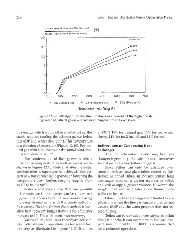
Figure 12.9—Enthalpy of combustion products as a percent of the higher heat-
ing value of natural gas as a function of temperature and excess air.
this energy which would otherwise be lost up the. at 450°F 18% for natural gas, 15% for coal-water
stack, requires cooling the exhaust gasses below slurry, 14% for no.2 fuel oil and 11% for coal.
the ADP and water dew point. This temperature
is a function of excess air (Figure 12.10). For nat- Indirect-contact Condensing Heat
ural gas with 10% excess air the initial condensa- Exchanger
tion temperature is 137°F. The indirect-contact condensing heat ex-
The condensation of flue gasses is also a changer is generally fabricated from corrosion-re-
function of temperature as well as excess air as sistant materials like Teflon and glass.
shown in Figure 12.10. Note that after the initial Since Teflon can only be extruded over
condensation temperature is achieved, the per- smooth surfaces and glass tubes cannot be fab-
cent of water condensed depends on lowering the ricated as finned tubes, an indirect contact heat
temperature even further, ranging roughly from exchanger requires a greater number of tubes
140°F to below 80°F. and will occupy a greater volume. However, the
Boiler efficiencies above 95% are possible weight may not be greater since thinner tube
if the moisture in flue gasses can be condensed, walls can be used.
Figure 12.11 shows how the recoverable energy Glass tube heat exchangers are limited to ap-
increases dramatically with the condensation of plications where the flue gas temperatures do not
flue gasses. The straight line characteristic of sen- exceed 4000F and the water pressure does not ex-
sible heat recovery bulges from a 2-5% efficiency ceed 50 psig.
increase to 11-15% with latent heat recovery. Teflon can be extruded over tubing as a thin
Various fuels, because of their hydrogen con- film (.015 inch). It can operate with flue gas tem-
tent, offer different opportunities for waste heat peratures up to 500°F, but 400°F is recommended
recovery as illustrated in Figure 12.12. It shows for continuous operation.