
Page 96 - Build a Remote Controlled Robot
P. 96
REMOTE CONTROL SYSTEM
TABLE 4-2. Control Combinations Using Transmitter Control Sticks
STICK POSITION ROBOT MOVEMENT 63
Right Left
Up Up Forward
Down Down Reverse
Center Center Stop
Up Down Circle right
Down Up Circle left
Up Center Turn right
Center Up Turn left
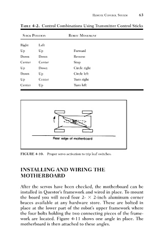
FIGURE 4-10. Proper servo activation to trip leaf switches.
INSTALLING AND WIRING THE
MOTHERBOARD
After the servos have been checked, the motherboard can be
installed in Questor’s framework and wired in place. To mount
the board you will need four 2- 2-inch aluminum corner
braces available at any hardware store. These are bolted in
place at the lower part of the robot’s upper framework where
the four bolts holding the two connecting pieces of the frame-
work are located. Figure 4-11 shows one angle in place. The
motherboard is then attached to these angles.