
Page 92 - Build a Remote Controlled Robot
P. 92
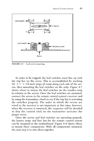
FIGURE 4-7. Leaf switch mounting.     REMOTE CONTROL SYSTEM   59


                                 In order to be tripped, the leaf switches must line up with
                              the trip bar on the servo. This is accomplished by stacking
                              10-   1-   1/8-inch strips of wood along each side of the ser-
                              vos, then mounting the leaf switches on the strip. Figure 4-7
                              shows where to mount the leaf switches on the wooden strip
                              in relation to the servos. Once the leaf switches are mounted,
                              connect the servos to the remote control system’s receiver and
                              by using the transmitter, check to see if the trip bar is activating
                              the switches properly. The order in which the servos are
                              wired to the receiver is not important at this time; however,
                              when the receiver is mounted, the sequence will be detailed
                              so that the control stick on the transmitter activates the
                              proper servo.
                                 Once the servos and leaf switches are operating properly,
                              the barrier strips and fuse box for the remote control system
                              can be mounted to the motherboard. Figure 4-4 shows where
                              to mount these components. With all components mounted,
                              the next step is to wire them together.