
Page 94 - Build a Remote Controlled Robot
P. 94
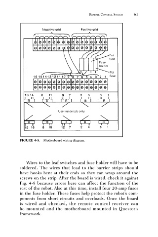
FIGURE 4-8. Motherboard wiring diagram.  REMOTE CONTROL SYSTEM  61


                                 Wires to the leaf switches and fuse holder will have to be
                              soldered. The wires that lead to the barrier strips should
                              have hooks bent at their ends so they can wrap around the
                              screws on the strip. After the board is wired, check it against
                              Fig. 4-8 because errors here can affect the function of the
                              rest of the robot. Also at this time, install four 20-amp fuses
                              in the fuse holder. These fuses help protect the robot’s com-
                              ponents from short circuits and overloads. Once the board
                              is wired and checked, the remote control receiver can
                              be mounted and the motherboard mounted in Questor’s
                              framework.