
Page 299 - Cam Design Handbook
P. 299
THB10 9/19/03 7:28 PM Page 287
CAM MANUFACTURING 287
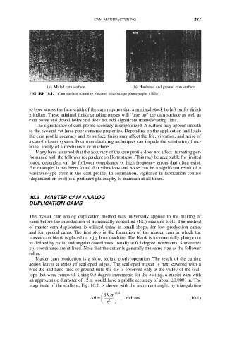
(a) Milled cam surface. (b) Hardened and ground cam surface
FIGURE 10.1. Cam surface scanning electron microscope photographs (100¥).
to bow across the face width of the cam requires that a minimal stock be left on for finish
grinding. These minimal finish grinding passes will “true up” the cam surface as well as
cam bores and dowel holes and does not add significant manufacturing time.
The significance of cam profile accuracy is emphasized. A surface may appear smooth
to the eye and yet have poor dynamic properties. Depending on the application and loads
the cam profile accuracy and its surface finish may affect the life, vibration, and noise of
a cam-follower system. Poor manufacturing techniques can impede the satisfactory func-
tional ability of a mechanism or machine.
Many have assumed that the accuracy of the cam profile does not affect its mating per-
formance with the follower (dependent on Hertz stress). This may be acceptable for limited
loads, dependent on the follower compliancy or high-frequency errors that often exist.
For example, it has been found that vibrations and noise can be a significant result of a
waviness-type error in the cam profile. In summation, vigilance in fabrication control
(dependent on cost) is a pertinent philosophy to maintain at all times.
10.2 MASTER CAM ANALOG
DUPLICATION CAMS
The master cam analog duplication method was universally applied to the making of
cams before the introduction of numerically controlled (NC) machine tools. The method
of master cam duplication is utilized today in small shops, for low production cams,
and for special cams. The first step is the formation of the master cam in which the
master cam blank is placed on a jig bore machine. The blank is incrementally plunge cut
as defined by radial and angular coordinates, usually at 0.5 degree increments. Sometimes
x-y coordinates are utilized. Note that the cutter is generally the same size as the follower
roller.
Master cam production is a slow, tedius, costly operation. The result of the cutting
action leaves a series of scalloped edges. The scalloped master is next covered with a
blue die and hand filed or ground until the die is observed only at the valley of the scal-
lops that were removed. Using 0.5 degree increments for the cutting, a master cam with
an approximate diameter of 12in would have a profile accuracy of about ±0.0001in. The
magnitude of the scallops, Fig. 10.2, is shown with the increment angle, by triangulation
12
Ê 8R s ˆ
Dq = Á c ˜ , radians (10.1)
Ë r 2 ¯
c