
Page 303 - Cam Design Handbook
P. 303
THB10 9/19/03 7:28 PM Page 291
CAM MANUFACTURING 291
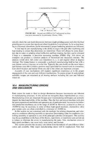
FIGURE 10.5. Ground cam (DRD) 4-5-6-7 polynomial accelera-
tion curve measured by Accelerometer (Norton, 1988).
odically check the cam track dimensions between rough grinding passes and after the final
grinding pass to ensure that significant wheel breakdown is not present. As far as heat treat-
ing is concerned, distortions can be minimized if proper hardening practices are followed.
A vital step in cam manufacturing is the ability to inspect the part after machining and
heat treating to ensure that distortions are minimized. There will always be some distor-
tion due to cutter or grinding wheel deflection and heat treating, but they can be tolerated
if kept to a minimum. A precision measuring machine (PMM) (Fig. 10.6 shows an
example) can produce a variation analysis of theoretical and measured contours. The
analysis would show full center axis translation (x, y, z) and angular offset in degrees
(timing). The timing feature is commonly a jig-bored manufacturing hold in line with a
cam feature such as a keyway or scribe line. Typically the cam dwells are the most impor-
tant features since this is where a positive stop is provided for external work to commence.
Cam dwell location and runout (from one end to the other) are important concepts.
Assembly of cam mechanisms still requires significant experience as to the proper
engagement of the cam and cam-follower mechanisms. To ensure proper fit and preload,
assembly torques are measured at all bearing surfaces including the cam and follower
wheel set.
10.4 MANUFACTURING ERRORS
AND DISCUSSION
Parts cannot be made to ideal or design dimensions because inaccuracies are inherent
in manufacturing processes. In this section we recognize these imperfections as errors.
Manufacturing errors are important because poor manufacturing techniques can seriously
impede the functional ability of the machine. Thus the best and newest machine tools plus
the most experienced machinists and operators are of particular need. Accuracies for indus-
trial production machinery are in the range of ±0.001in. However, accuracies as close as
±0.0003in may be necessary in some of these high-speed machines. Automotive valve
gear system cams are often controlled to a tolerance of ±0.0001in.
In this section we are concerned with the methods for relating dimensions and toler-
ances to conditions affecting assembly or operation. Determining value for conditions con-
trolling assembly or operation is one of the principal activities of designers. This activity
may be accomplished on the basis of the theory, experiment, or experience and carried out
to reduce or eliminate the errors in manufacturing the parts. Also, mechanism errors in
high-speed machinery can cause early wear, noise, and fracture.
This section presents the accuracy (deviation from theoretical) of cam-follower fabri-
cation and assembly. Only major manufacturing errors will be emphasized. Note that