
Page 301 - Cam Design Handbook
P. 301
THB10 9/19/03 7:28 PM Page 289
CAM MANUFACTURING 289
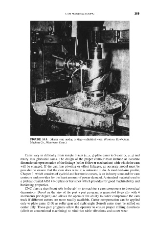
FIGURE 10.3. Master cam analog cutting—cylindrical cam. (Courtesy Rowbottom
Machine Co., Waterbury, Conn.)
Cams vary in difficulty from simple 3-axis (x, y, z) plate cams to 5-axis (x, y, z) and
rotary axis globoidal cams. The design of the proper contour must include an accurate
dimensional representation of the linkage (roller-follower mechanism) with which the cam
will be engaged. If the cam has pivoting or offset linkages, an accurate model must be
provided to ensure that the cam does what it is intended to do. A modified-sine profile,
Chapter 3, which consists of cycloid and harmonic curves, is an industry standard for cam
contours and provides for the least amount of power demand. A standard material used is
a preheat-treated AISI 4140 plate or bar stock which provides for good machinability and
hardening properties.
CNC plays a significant role in the ability to machine a cam component to theoretical
dimensions. Based on the size of the part a part program is generated (typically with 4
increments per degree) and allows the operator the ability to cutter compensate the cam
track if different cutters are more readily available. Cutter compensation can be applied
only to plate cams (2-D) as roller gear and right-angle (barrel) cams must be milled on
center only. These part programs allow the operator to ensure proper milling directions
(climb or conventional machining) to minimize table vibrations and cutter wear.