
Page 300 - Cam Design Handbook
P. 300
THB10 9/19/03 7:28 PM Page 288
288 CAM DESIGN HANDBOOK
Cutter
O 2
s
R g
O 1 Cam
profile
r c
Dq
Cam center
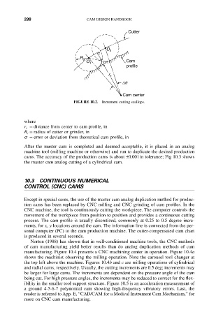
FIGURE 10.2. Increment cutting scallops.
where
r c = distance from center to cam profile, in
R c = radius of cutter or grinder, in
s = error or deviation from theoretical cam profile, in
After the master cam is completed and deemed acceptable, it is placed in an analog
machine tool (milling machine or otherwise) and run to duplicate the desired production
cams. The accuracy of the production cams is about ±0.001in tolerance; Fig 10.3 shows
the master cam analog cutting of a cylindrical cam.
10.3 CONTINUOUS NUMERICAL
CONTROL (CNC) CAMS
Except in special cases, the use of the master cam analog duplication method for produc-
tion cams has been replaced by CNC milling and CNC grinding of cam profiles. In the
CNC machine, the tool is continuously cutting the workpiece. The computer controls the
movement of the workpiece from position to position and provides a continuous cutting
process. The cam profile is usually discretized, commonly at 0.25 to 0.5 degree incre-
ments, for x, y locations around the cam. The information line is connected from the per-
sonal computer (PC) to the cam production machine. The cutter-compensated cam chart
is produced in several seconds.
Norton (1988) has shown that in well-conditioned machine tools, the CNC methods
of cam manufacturing yield better results than do analog duplication methods of cam
manufacturing. Figure 10.4 presents a CNC machining center in operation. Figure 10.4a
shows the machinist observing the milling operation. Note the carousel tool changer at
the top left above the machine. Figures 10.4b and c are milling operations of cylindrical
and radial cams, respectively. Usually, the cutting increments are 0.5 deg; increments may
be larger for large cams. The increments are dependent on the pressure angle of the cam
being cut. For high pressure angles, the increments may be reduced to correct for the flex-
ibility in the smaller tool support structure. Figure 10.5 is an acceleration measurement of
a ground 4-5-6-7 polynomial cam showing high-frequency vibratory errors. Last, the
reader is referred to App. E, “CAD/CAM for a Medical Instrument Cam Mechanism,” for
more on CNC cam manufacturing.