
Page 306 - Cam Design Handbook
P. 306
THB10 9/19/03 7:28 PM Page 294
294 CAM DESIGN HANDBOOK
produced by a milling cutter taking too large a feed in the continuous generation of a cam.
See Harris (1991) for the effect of waviness on vibration and noise.
Another kind of error is the misalignment of assembled parts. Misalignment of parts
is a fault that should not be tolerated. The parts should be fitted properly for machine
running conditions. The sources of misalignment include inaccurate machining or large
tolerances in the mounting surfaces. Misalignment produces a reduced fatigue life in cam-
follower contacting surfaces. In the roller follower there are two types of misalignment:
(1) the cam follower axis is not parallel to the plane of rolling, e.g., the axis is lifted on
one end. This condition will shift the contact area to one end of the outer ring. (2) Also,
the cam-follower axis is not perpendicular to the direction of motion; in other words, the
axis is skewed. Misalignment can be accommodated by using crowned followers. Straight
rollers produce an elliptical contact stress surface, and crowned runners produce a circu-
lar stress surface. Also, a large radius crown should be used.
10.4.5 Probabilistic Model of Cam Profile
The stochastic nature of the cam profile used by Kim and Newcombe (1982) is presented
in this section. Also, the designer is referred to Chap. 12, which shows the combined effects
of the cam follower dynamics and the probabilistic model of the cam profile.
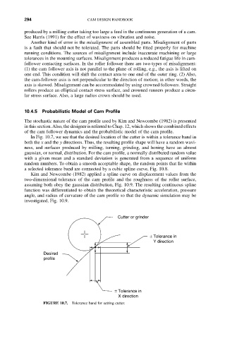
In Fig. 10.7, we see that the desired location of the cutter is within a tolerance band in
both the x and the y directions. Thus, the resulting profile shape will have a random wavi-
ness, and surfaces produced by milling, turning, grinding, and honing have an almost
gaussian, or normal, distribution. For the cam profile, a normally distributed random value
with a given mean and a standard deviation is generated from a sequence of uniform
random numbers. To obtain a smooth acceptable shape, the random points that lie within
a selected tolerance band are connected by a cubic spline curve, Fig. 10.8.
Kim and Newcombe (1982) applied a spline curve on displacement values from the
two-dimensional tolerance of the cam profile and the roughness of the roller surface,
assuming both obey the gaussian distribution, Fig. 10.9. The resulting continuous spline
function was differentiated to obtain the theoretical characteristic acceleration, pressure
angle, and radius of curvature of the cam profile so that the dynamic simulation may be
investigated, Fig. 10.9.
Cutter or grinder
± Tolerance in
Y direction
Desired
profile
± Tolerance in
X direction
FIGURE 10.7. Tolerance band for setting cutter.